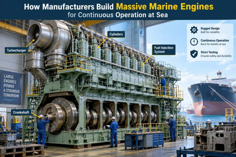

A container ship may leave port with a schedule measured in days or weeks, then spend long stretches beyond the reach of shore-based repair shops. Beneath the accommodation block, its main engine must keep converting fuel into controlled power through heat, vibration, weather, and changing loads.
That expectation makes a large marine engine very different from a large road engine. It is not simply made bigger. Its materials, geometry, manufacturing sequence, inspection methods, and maintenance access are all designed around the reality that a failure at sea can disrupt propulsion, safety, and cargo operations.
For engineering students, the manufacturing route explains why engine components look the way they do. For working professionals, it connects workshop decisions—such as a machining tolerance or a casting repair procedure—to reliability months or years later.
Building these engines is a long chain of controlled decisions. The finished machine is the visible result; the less visible product is confidence that every critical surface, passage, joint, and measurement can endure continuous service.
⚓ What Makes a Marine Engine “Massive”
Large low-speed two-stroke diesel engines are commonly used as direct-drive main engines on deep-sea merchant ships. Their dimensions are governed by the propeller they must turn efficiently, often at relatively low rotational speed and with very high torque.
A cylinder bore can be close to a metre in the largest designs, while an individual piston, connecting rod, or cylinder cover may require dedicated lifting arrangements. Medium-speed four-stroke engines are smaller and faster, but they still use components far beyond the scale of automotive production.
Size changes the manufacturing problem. A small distortion, inclusion, or handling error that might be tolerable in a light component can become serious when loads, heat flows, and stored energy are large.
🧭 Designing for a Life Away from the Workshop
Manufacturers design around operating realities rather than laboratory perfection. The engine must tolerate variable ambient temperatures, fuel quality differences within specification, hull vibration, transient maneuvering loads, and long intervals between major overhauls.
Maintainability is designed into the structure. Inspection doors, lifting points, removable covers, access to bearings, and clear measurement references allow ship engineers and service technicians to inspect and renew parts without dismantling unrelated systems.
This does not mean every repair is possible onboard. Crankshaft machining, extensive welding, and many precision alignments need specialist facilities. The practical aim is to detect deterioration early and make planned replacement feasible.
📐 Starting with the Duty Cycle
Before metal is ordered, designers define the intended duty: propulsion, electrical generation, auxiliary service, or a combination. A main engine may operate near a selected service load for long periods, while a generator engine can experience frequent load steps as pumps, thrusters, or cargo equipment switch on.
These patterns influence bearing size, cooling capacity, turbocharger matching, fuel-system design, and fatigue calculations. An engine optimized only for peak output would be a poor answer to continuous marine duty.
- Steady propulsion service emphasizes efficient, durable operation at the intended speed range.
- Generator service emphasizes speed governing, response to electrical load changes, and redundancy.
- Harbor and maneuvering service emphasizes controllability at low load and during reversals or rapid changes.
🧪 Selecting Metals for Heat, Load, and Corrosion
Material selection is a compromise among strength, toughness, wear resistance, castability, machinability, cost, and repairability. Engine frames and blocks commonly use cast iron or fabricated steel structures; crankshafts use high-strength forged steel; liners use specially formulated cast iron for wear and thermal behavior.
Hot components face a different environment from structural ones. Exhaust valves, for example, need alloys that retain useful strength and resist oxidation at elevated temperature. Piston rings need surfaces that control wear and lubrication rather than simply being as hard as possible.
Seawater is usually kept out of the engine’s internal cooling circuit by using treated fresh water, but external coolers and connected pipework still make corrosion control part of the wider design problem.
🔥 Why Foundry Work Is the First Reliability Test
Many major engine parts begin as castings. A cylinder block, bedplate section, frame box, cylinder cover, or exhaust housing may have internal shapes that would be difficult or wasteful to machine from a solid block.
In a foundry, molten metal fills a mould containing cores that create passages and cavities. The process must control filling, temperature, solidification, and feeding of shrinking metal. Poor control can leave porosity, shrinkage cavities, inclusions, or residual stresses.
These defects are not always visible from the outside. That is why foundry practice and subsequent non-destructive examination are inseparable from engine reliability, not merely cosmetic quality work.
🏗️ Forging the Parts That Carry Cyclic Load
Crankshafts, connecting rods, piston rods, and selected fasteners are often forged because forging can produce a favorable grain flow and dense structure for heavily loaded components. The starting ingot or billet is heated and shaped under large presses or hammers.
Forging is followed by controlled cooling and heat treatment. The objective is not maximum hardness alone; it is a balanced microstructure with sufficient strength and toughness for repeated loading.
Crankshaft manufacture is particularly demanding because each crank throw must ultimately sit in the intended position relative to every journal. That geometry is established over several machining and measurement stages, not in one operation.
🌡️ Heat Treatment Sets the Internal Structure
Steel’s properties depend on composition and thermal history. Processes such as normalizing, quenching, tempering, stress relieving, and case hardening alter microstructure and therefore strength, ductility, residual stress, or surface wear resistance.
A part can be dimensionally correct but metallurgically unsuitable. Conversely, aggressive hardening may raise wear resistance while making a component less tolerant of shock or stress concentration if not properly tempered.
Manufacturers use controlled furnace cycles, load arrangements, temperature recording, and specified cooling methods. Test pieces or representative samples may be examined to confirm that the required properties have been achieved.
🔍 Inspecting What the Eye Cannot See
Non-destructive testing, often abbreviated NDT, looks for defects without sacrificing the finished component. The chosen method depends on material, shape, expected defect type, and access.
| Method | Useful for | Practical limitation |
|---|---|---|
| Ultrasonic testing | Internal discontinuities in thick sections | Interpretation depends on geometry and operator procedure |
| Magnetic particle testing | Surface and near-surface flaws in ferromagnetic steel | Not suitable for non-magnetic materials |
| Dye penetrant testing | Surface-breaking defects on suitable clean surfaces | Cannot reveal buried defects |
| Radiographic testing | Internal casting features and selected welds | Requires controlled safety arrangements and access |
NDT is not a magic pass/fail ritual. An indication must be assessed against acceptance criteria, component location, loading, and manufacturing records. A tiny indication in one location may have a different significance from one near a highly stressed fillet.
🧱 Machining the Bedplate and Engine Structure
The bedplate forms the lower foundation of many large engines. It supports main bearings and transfers loads into the ship’s foundation through holding-down arrangements. Its machined bearing saddles must be accurately positioned so the crankshaft is supported as intended.
Frame sections, tie-rod paths, guide planes, and cylinder seating surfaces are machined in relation to defined datums—reference surfaces or axes used to control geometry. Without a disciplined datum strategy, individually accurate parts may not assemble accurately.
Large machining centers, boring machines, and portable equipment can all be involved. Temperature matters: a long steel structure expands enough with temperature change to affect precision measurements, so measurement conditions and compensation procedures are controlled.
🌀 The Crankshaft: Geometry Under Enormous Load
The crankshaft converts the pistons’ reciprocating motion into rotary torque. It experiences bending, torsion, and cyclic loading, while its journals run on a thin hydrodynamic oil film rather than touching the bearing surface during healthy operation.
After rough machining, journals are finished to specified dimensions, surface quality, and roundness. Fillet radii receive special attention because abrupt changes in section create stress concentration. Oil drillings must be clean, correctly formed, and connected to deliver lubricant where required.
Final inspection can include dimensional measurement, surface examination, balancing considerations, and checks of oil passages. A crankshaft is expensive, but its true value is that it preserves accurate motion through millions of load cycles.
🛢️ Bearings Are Built Around an Oil Film
Marine engine bearings are engineered systems, not just soft metal shells. A typical shell has a steel backing and a bearing lining selected to embed small contaminants, conform slightly during running-in, and survive temporary abnormal conditions better than the shaft surface.
During normal hydrodynamic lubrication, rotation draws oil into a converging clearance and generates pressure that separates journal and bearing. Clearance, oil viscosity, shaft finish, load, and oil supply all influence that film.
Manufacturing and assembly must therefore control bearing crush, locating features, bore geometry, and cleanliness. A blocked oil drilling or incorrect clearance can defeat an otherwise excellent bearing material.
🧰 Cylinder Liners Need a Carefully Engineered Surface
The cylinder liner is both a pressure boundary and a sliding surface for piston rings. It must transfer heat to cooling water, resist wear, maintain a stable bore, and retain a thin lubricating film.
Its bore is finish-machined and honed to create a controlled surface texture. The microscopic valleys retain lubricant, while the plateau-like bearing areas support ring contact. A surface that is too smooth may struggle to retain oil; one that is too rough can accelerate ring and liner wear.
Ports in two-stroke liners add another challenge. Their edges and shape must be produced accurately because they influence gas flow and must not damage rings as they pass.
🔩 Pistons, Rings, and the Moving Combustion Chamber
Large marine pistons may be assembled from several parts, with materials chosen according to the temperatures and loads in each region. Cooling oil may circulate through internal spaces to carry heat away from the crown, where combustion exposure is greatest.
Piston rings seal combustion gas, control lubricant distribution, and conduct some heat to the liner. Their free shape, installed gap, coating, and groove clearance are carefully specified. Rings need enough contact pressure to seal, but excessive friction creates heat and wear.
The piston, rings, liner, and lubrication system must be treated as one interface. Changing a single feature—such as oil feed rate or liner finish—can alter the behavior of all the others.
💨 Cylinder Covers and Exhaust-Valve Challenges
The cylinder cover contains combustion pressure and commonly carries valves, injectors, starting-air connections, and cooling passages. Its design requires strong sections around openings while avoiding sharp stress raisers and ensuring coolant reaches hot zones.
Exhaust valves operate in a severe combination of heat, corrosion products, impact, and sliding contact. Manufacturers use suitable high-temperature materials, accurate seat geometry, cooling arrangements where applicable, and robust actuation mechanisms.
Deposits, poor sealing, incorrect valve timing, or inadequate cooling can damage a valve even if it was manufactured correctly. Continuous-duty reliability always depends on both build quality and operating conditions.
⛽ Fuel Systems Demand Clean, Precise Manufacture
Fuel injection equipment meters and times fuel delivery under high pressure. Pumps, injectors, valves, and precision plungers depend on extremely clean assembly conditions because fine clearances can be damaged by contamination.
Modern electronically controlled engines add sensors, actuators, control valves, and software-managed timing. The manufacturing challenge expands from mechanical accuracy to traceable calibration and functional verification of the complete system.
Fuel quality management remains important in service. Separators, filters, heating, viscosity control, and water removal protect precision components from abrasive particles and poor combustion behavior.
🌬️ Turbochargers Multiply the Air Supply
A turbocharger uses energy from exhaust gas to drive a compressor that supplies pressurized intake air. More air supports efficient combustion and helps the engine produce the required power without making every cylinder much larger.
The turbine and compressor rotor turns at very high speed, so balance quality, bearing condition, clean air flow, and lubrication are critical. Manufacturing includes precision machining and balancing, while service demands attention to filter condition and oil cleanliness.
Turbocharging brings efficiency benefits, but it also couples the air and exhaust sides closely. Fouling, leakage, or poor matching can reduce air delivery and raise thermal stress elsewhere in the engine.
💧 Cooling Passages Must Remove Heat Evenly
Cooling systems do more than prevent overheating. They control metal temperatures so clearances, lubricant behavior, material strength, and thermal stresses remain within the intended range.
Manufacturers shape water jackets and drilling routes to reach regions around liners, covers, valve seats, and exhaust areas. Uneven cooling can create local hot spots, distortion, cracking risk, or deposits that progressively reduce heat transfer.
During production, passages must be cleaned of core sand, machining debris, and loose scale. Pressure testing helps reveal leaks before the engine enters service, but correct water treatment is still essential once it is aboard ship.
🧼 Cleanliness Is a Manufacturing Dimension
A particle that is harmless on a workshop floor can be destructive inside a fuel pump, hydraulic actuator, bearing oil gallery, or turbocharger bearing. For that reason, cleaning is an engineered process with defined solvents or wash methods, drying, protection, and inspection.
Open ports are capped, machined surfaces are protected, and components are stored to prevent corrosion and accidental contamination. Final flushing of lubricating-oil circuits is especially important after fabrication and assembly work.
Cleanliness cannot be added at the last minute. It relies on keeping contamination out throughout machining, handling, assembly, and preservation.
📏 Tolerances Control the Spaces Between Parts
A tolerance defines the permitted variation from a nominal dimension. In a marine engine, tolerances manage not only fit but also functional clearances: bearing oil-film space, piston-ring side clearance, valve guide clearance, gear backlash, and injector seating.
Too little clearance can lead to seizure when temperature rises. Too much can reduce oil pressure, increase impact loading, weaken sealing, or allow unwanted motion. The correct value depends on material pairings, temperature gradients, lubrication, and intended operating regime.
Measurements are only useful when instruments are calibrated and the method is repeatable. A bore gauge, micrometer, dial indicator, and laser alignment system each answer different questions; selecting the wrong tool can create misleading confidence.
🧷 Fasteners and Tie Rods Hold the Load Path Together
Large engines use highly loaded studs, bolts, and, in many designs, long tie rods that clamp the structure from bedplate to upper frame. Their preload keeps joint faces in compression as combustion and inertia loads vary.
Correct tightening is more complicated than applying a torque value. Hydraulic tensioning may be used to stretch a fastener directly, reducing uncertainty caused by thread and nut friction. Tightening sequence, lubrication, elongation measurement, and specified pressure all matter.
A damaged thread, wrong lubricant, or mixed fastener can change achieved preload. These apparently small workshop errors can affect alignment, joint integrity, and fatigue life.
🏭 Assembly Turns Components into One Machine
Assembly follows a planned sequence because later parts depend on earlier alignment. The bedplate is prepared, main bearing shells installed, the crankshaft lowered and checked, then frames, guides, pistons, covers, cam or electronic actuation equipment, and auxiliaries are added.
At each stage, technicians document critical checks. These may include crankshaft deflection readings, bearing clearances, piston-rod alignment, timing positions, valve clearances, and safety-device installation.
Large components are handled by cranes and purpose-built fixtures. Safe lifting is also a quality issue: uncontrolled movement can damage precision surfaces, distort parts, or introduce hidden impact damage.
📍 Alignment Continues Beyond the Factory Floor
An engine may be assembled accurately at the factory but still require careful installation on the vessel. The ship’s foundation, chocks or resin bedding, holding-down bolts, shaftline, gearbox where fitted, and propeller all influence final alignment.
Hull deflection changes with loading, dry-docking, temperature, and sea conditions. Designers and installers account for this through specified alignment targets and measurement procedures rather than assuming the hull is a perfectly rigid platform.
Misalignment can raise bearing loads and produce abnormal wear patterns. It is a system problem, so correction requires looking beyond the engine itself.
🧯 Pressure Tests Prove Containment Before Operation
Cooling spaces, fuel lines, lubrication circuits, starting-air components, and other pressure-containing parts are tested according to the applicable design and quality procedures. The purpose is to verify that joints, castings, plugs, and passages contain the intended fluid without unacceptable leakage.
Testing must use controlled pressure, suitable barriers, trained personnel, and documented acceptance criteria. Pressurized systems store energy, so a casual test arrangement creates a safety risk as well as unreliable results.
A successful pressure test confirms containment at that stage. It does not replace correct operation, periodic inspection, or protection against vibration and corrosion in service.
🧪 Factory Acceptance Testing Connects Design to Reality
Before delivery, engines are run and monitored under a defined test program. The exact scope varies by engine type, contract, classification requirements, and intended service, but it commonly checks operation across a range of loads and confirms key pressures, temperatures, speed response, and alarms.
Technicians look for stable combustion, correct lubrication, adequate cooling, vibration behavior, governor response, and abnormal noise or leakage. Data are compared with expected limits and the manufacturer’s documented procedures.
Testing is not merely a ceremonial final run. It can reveal assembly errors, sensor faults, piping restrictions, timing issues, or control-system problems while the engine is still near the people and equipment needed to correct them.
📚 Documentation Makes Future Maintenance Possible
Each engine has a technical identity that extends beyond its serial number. Material certificates, machining records, inspection reports, torque or tension records, test results, settings, and component traceability can all matter during troubleshooting or warranty investigation.
Onboard manuals then translate design intent into maintenance tasks: what to inspect, how to measure wear, which limits apply, and which parts must not be mixed. Clear documentation prevents technicians from relying solely on memory or habit.
Digital records can improve retrieval and trend monitoring, but only if entries are accurate and usable. A complete but unreadable data set does not support good maintenance decisions.
🔧 Commissioning Verifies the Installed System
Factory testing cannot fully reproduce shipboard operation. Commissioning verifies the engine with its actual cooling circuits, fuel preparation equipment, control interfaces, shafting arrangement, alarms, and vessel electrical systems.
Checks often include direction of rotation, interlocks, emergency stops, remote control functions, alarm set points, leak checks, and response during operational transitions. For propulsion plants, the interaction between engine, propeller, and hull becomes significant.
Commissioning should be methodical rather than rushed. Correcting a small pipe support, sensor connection, or control logic issue early is generally far easier than investigating an intermittent fault at sea.
⚠️ Common Shortcuts That Create Long-Term Problems
Many failures trace back not to exotic defects but to ordinary discipline failures. Skipping a cleaning step, using an unverified measurement, substituting an unapproved seal, or failing to record a critical setting can plant a delayed problem.
- Using force to assemble a part that should slide into position can mask misalignment or an incorrect component.
- Reusing damaged fasteners or seals can compromise preload or fluid containment.
- Ignoring a minor leak during testing can allow vibration and thermal cycling to turn it into a larger defect.
- Changing one component without checking its mating surfaces can create rapid wear after restart.
Good manufacturing culture treats deviations as engineering information. The correct response is to assess, document, and disposition them—not simply make them disappear from view.
🧠 Condition Monitoring Extends the Manufacturing Mindset
Once the engine enters service, condition monitoring continues the original quality strategy. Oil analysis can indicate contamination or wear metals; temperature and pressure trends can reveal developing restrictions; vibration data can help identify rotating-equipment issues.
These methods rarely diagnose every fault on their own. Their value lies in trends and correlation with inspection findings, operating history, and manufacturer guidance. A single abnormal reading should prompt investigation, not automatic assumptions.
For crews, this means keeping reliable logs and understanding normal behavior. A well-built engine still needs observant operation to remain dependable.
🌱 Efficiency and Emissions Change the Build Requirements
Pressure to reduce fuel consumption and emissions has changed marine-engine hardware. Electronic control, improved fuel injection, optimized combustion chambers, exhaust-gas treatment interfaces, alternative-fuel arrangements, and waste-heat systems add components and integration work.
Some solutions improve one part of performance while creating new maintenance or material challenges. Alternative fuels, for example, can require different sealing strategies, fuel-system materials, ventilation provisions, and safety arrangements.
Manufacturers therefore build flexibility into certain engine platforms, but retrofits must be assessed as complete systems. A modification that fits physically may still alter thermal loads, control logic, class requirements, or maintenance needs.
👷 Skills Matter as Much as Machines
Large CNC machines, automated measurement, and digital production planning improve consistency, yet skilled people remain central. Foundry workers judge process behavior, machinists interpret measurement results, assemblers recognize abnormal fits, and test engineers connect data to physical causes.
Marine engineering work also depends on disciplined communication between design, purchasing, production, quality, shipyard, and vessel operators. A drawing note has little value if its purpose is misunderstood at the point of work.
For students, the lesson is encouraging: manufacturing knowledge is not separate from design knowledge. Understanding how a part is made leads to designs that can be inspected, assembled, repaired, and trusted.
🧩 The Core Principle: Reliability Is Manufactured in Layers
A massive marine engine reaches continuous service capability through layers of protection: appropriate design margins, controlled materials, sound castings and forgings, heat treatment, precision machining, clean assembly, documented testing, correct installation, and informed maintenance.
No single inspection can compensate for every earlier mistake. Likewise, no excellent component can guarantee system reliability if lubrication, cooling, alignment, or operating practice is poor.
The most useful way to view the process is as a chain of evidence. Every controlled operation provides evidence that the next operation starts from a sound condition, until the engine is ready to deliver power far from shore.
Manufacturers build dependable marine engines not by making parts merely large, but by controlling every interface that lets those parts work together continuously at sea. That is the standard behind the machinery that keeps ships moving across long, demanding voyages. ⚓🔧🌊