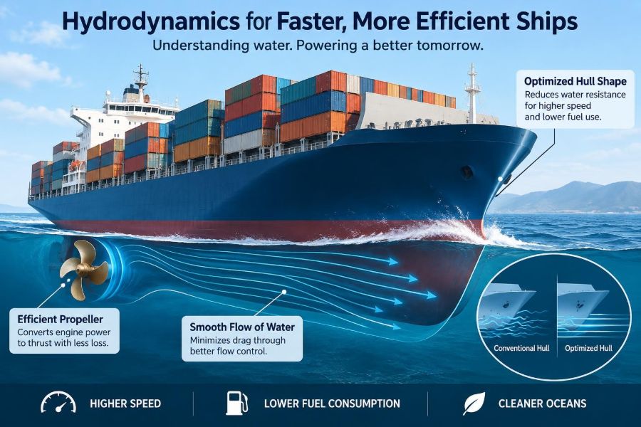

A container ship leaving port can appear almost effortless. Its engines maintain a steady rhythm, the hull cuts through a swell, and thousands of tonnes of cargo move across the ocean on a remarkably small amount of fuel per tonne carried.
That apparent simplicity hides a demanding engineering problem. Water is dense, viscous, and restless; every metre of hull, every appendage below the waterline, and every propeller blade changes how energy is spent.
For seafarers, naval architects, and marine engineers, hydrodynamics is not abstract theory. It affects fuel consumption, vibration, schedule reliability, cavitation damage, cargo capacity, and emissions.
Modern ships became faster and more efficient through a series of discoveries about how water flows, how waves form, and how a ship’s hull and propeller interact. Many of the best ideas are now so familiar that it is easy to forget they were major breakthroughs.
🌊 Hydrodynamics: The Science Behind Resistance
Hydrodynamics is the study of fluids in motion and the forces they exert. In ship design, it explains the resistance opposing forward motion and the thrust needed to overcome it.
A vessel does not push only water directly ahead. It also creates waves, shears water along its wetted surface, forms vortices around changes in shape, and disturbs the inflow to its propeller. Each effect consumes energy.
The central design task is therefore not simply to make a hull look streamlined. It is to achieve the required speed, carrying capacity, stability, strength, manoeuvrability, and safety with the lowest practical power demand.
⚖️ The First Great Insight: Resistance Has Several Causes
Early ship development benefited enormously from separating total resistance into components. This made it possible to improve a hull systematically instead of treating drag as one mysterious force.
The main components include frictional resistance, wave-making resistance, viscous pressure resistance, air resistance, and the resistance caused by appendages such as rudders, shaft brackets, and bilge keels. They overlap in real flow, but the classification remains extremely useful.
At ordinary merchant-ship speeds, friction and wave formation often dominate. At higher speeds, wave effects can rise sharply, changing which hull form is most suitable.
🧪 William Froude and the Model-Test Revolution
William Froude’s nineteenth-century work established a practical method for predicting full-scale ship performance from scale-model experiments. His key insight was that a model must reproduce the relationship between speed, length, and gravity-driven wave effects.
That relationship is expressed through the Froude number, usually written as speed divided by the square root of gravitational acceleration times waterline length. Matching this number allows a model and a full-scale ship to create comparable wave patterns.
Froude also developed ways to estimate friction separately. Together, these ideas transformed ship design from a mainly empirical craft into an experimental engineering discipline.
📐 Why Scale Models Cannot Copy Everything Perfectly
A model basin cannot make every physical effect scale in exactly the same way. Water viscosity matters to friction, while gravity strongly controls waves; the relevant dimensionless quantity for viscous flow is the Reynolds number.
A small model running at the Froude-matched speed does not usually match the full-scale Reynolds number. Designers therefore measure model resistance, estimate frictional differences with accepted methods, and extrapolate cautiously to full scale.
This limitation is not a flaw in model testing; it is a reminder that predictions need engineering judgment. Surface roughness, scale effects, wind, sea state, and propeller interaction can all create differences between tank results and service performance.
🫧 Frictional Resistance and the Boundary Layer
As a ship moves, a thin region of water next to the hull is slowed by viscosity. This region is called the boundary layer. Its behaviour determines a large share of skin-friction resistance.
Near the bow, flow may initially be smooth or laminar. Over most of a large working hull, however, it becomes turbulent. Turbulent flow has greater mixing and generally higher friction, but it can also remain attached to curved surfaces more reliably than laminar flow.
This explains why a clean, fair hull matters so much. Even small increases in roughness disturb the boundary layer over thousands of square metres of wetted area.
🧽 Smooth Hulls, Coatings, and Fouling Control
A freshly coated hull is not merely visually tidy. Its smoothness helps limit friction, while an effective antifouling system slows the attachment of organisms such as slime, algae, and barnacles.
Biofouling increases surface roughness and can materially raise the power required at a given speed. The operational response may be higher fuel consumption, reduced speed, or both.
Hull cleaning and coating selection must be treated as lifecycle decisions. Aggressive cleaning can damage coatings, and local environmental rules may restrict methods or discharge. The sensible aim is controlled roughness management, not a one-time cosmetic finish.
🌐 Wave-Making Resistance and Hull Speed
A displacement ship creates a system of bow and stern waves. Energy transferred into these waves is energy unavailable for moving cargo efficiently, producing wave-making resistance.
As speed rises, the wavelengths change. At certain speed-to-length ratios, the hull can appear trapped between its own wave crests, and resistance rises rapidly. This is the origin of the useful but simplified expression “hull speed.”
Hull speed is not a hard barrier. Long, slender vessels, planing craft, hydrofoils, and semi-displacement forms behave differently. Still, the concept explains why a modest speed increase can require a disproportionately large increase in installed power.
📏 Length, Slenderness, and the Speed-Length Trade-Off
For a given displacement, a longer hull can often travel faster before wave-making resistance becomes severe. This is one reason many fast ferries and naval vessels use relatively slender forms.
But extra length adds structural weight, construction cost, berth constraints, and sometimes more wetted area. A very narrow hull may also reduce transverse stability or limit cargo arrangement.
There is no universally efficient length-to-beam ratio. A slow bulk carrier, a high-speed catamaran, and an offshore patrol vessel face different constraints and therefore arrive at different hydrodynamic compromises.
🛶 Bulbous Bows and Wave Interference
The bulbous bow is one of the most visible hydrodynamic developments on modern displacement ships. Positioned below the waterline near the bow, it produces its own wave system.
When designed for a particular draft and speed range, the bulb wave can partly cancel the main bow wave. This destructive interference reduces wave-making resistance and may reduce power demand.
A bulb is not automatically beneficial. Its performance depends on loading condition, operating speed, and hull geometry. A ship that frequently sails far from its design draft or speed may gain little, which is why bulb geometry must reflect the actual operating profile.
🔄 Stern Shape and Clean Flow to the Propeller
The stern has two jobs: it must let water leave the hull with minimal loss and deliver a uniform, stable flow to the propeller. A poor stern arrangement can create separation, vortices, vibration, and uneven propeller loading.
Naval architects use fair lines, carefully shaped buttocks, and appropriate transom geometry to manage the flow. The objective is not always perfectly uniform wake, since some wake characteristics can be used beneficially in propeller design.
What matters is a wake field that is predictable and compatible with the propeller, rudder, and shafting. This is a strong example of why hull and propulsor should be designed as one system.
🌀 The Propeller Transformed Marine Transport
The screw propeller replaced older propulsion arrangements because it can convert rotational shaft power into forward thrust efficiently and compactly. Its development made reliable ocean-going steamships practical on a far larger scale.
A propeller works by accelerating water aft. In broad terms, thrust comes from the pressure difference between the blade’s forward and aft faces, much as an aerofoil develops lift in air.
Efficient propulsion does not mean accelerating a small mass of water to an extreme velocity. It generally means accelerating a larger mass of water by a smaller amount, which is why propeller diameter and rotational speed matter so much.
⚙️ Propeller Diameter, Pitch, and Rotational Speed
A larger, slower-turning propeller can often achieve better efficiency because it moves a larger flow of water with less unnecessary kinetic energy in the wake. Draft limits, hull clearance, and machinery layout set practical boundaries.
Pitch is the theoretical distance a propeller would advance in one revolution through a solid material. Real water allows slip, so actual advance is less than theoretical pitch.
Fixed-pitch propellers are robust and efficient at their design condition. Controllable-pitch propellers add operational flexibility, particularly where frequent manoeuvring or varied loads matter, but introduce mechanical complexity in the hub.
💥 Cavitation: When Low Pressure Becomes Damage
Cavitation occurs when local pressure on a propeller blade falls low enough for vapour-filled cavities to form. When those cavities collapse in higher-pressure regions, they can create noise, vibration, erosion, and reduced thrust.
It is not simply a sign of a bad propeller. Cavitation risk increases with high loading, high rotational speed, poor inflow, shallow submergence, and certain operating conditions.
Designers manage it by selecting diameter, blade area, blade sections, pitch distribution, and rotational speed carefully. Operators also help by avoiding unnecessary high-load conditions and investigating sudden changes in vibration or noise.
🎵 Noise and Vibration as Flow Diagnostics
Propeller-induced pressure pulses can excite vibration in the hull, shaft line, and accommodation spaces. On passenger ships, naval vessels, research platforms, and offshore support vessels, comfort or acoustic discretion may be as important as fuel use.
Hydrodynamic noise also matters environmentally because underwater sound travels efficiently and can affect marine life. Reducing it requires more than fitting insulation after construction; it begins with flow quality and propeller design.
Unusual propeller singing, stern vibration, or a change in machinery loading should be treated as useful operational evidence. The cause may lie in fouling, damage, altered draft, cavitation, bearings, or wake disturbance.
🧩 Hull–Propeller–Rudder Interaction
Open-water propeller tests describe propeller performance in a uniform incoming flow. Behind a real hull, the propeller operates in a slower, non-uniform wake, while the propeller changes the pressure field around the stern and rudder.
Engineers describe these linked effects using interaction quantities such as wake fraction, thrust deduction, and relative rotative efficiency. The terminology can seem specialized, but the message is straightforward: testing parts in isolation does not reveal full-system efficiency.
A rudder placed in the propeller slipstream can gain steering force, yet it also adds drag. Its profile, area, position, and integration with the stern all influence the overall result.
🧭 Energy-Saving Devices at the Stern
Devices such as pre-swirl stators, ducts, fins, and rudder bulbs aim to recover or redirect energy that would otherwise be lost in the propeller wake. Some improve inflow; others reduce rotational energy left in the slipstream.
They can be effective when matched to a specific hull and operating range. However, a device that works well on one vessel cannot be assumed to work equally well on another, even if the ships look similar.
Retrofit decisions should consider verified operating data, installation effects, structural support, inspection access, fouling exposure, and any influence on manoeuvring. The best device is one that improves the ship’s real duty cycle, not only a model-test result.
🏗️ The Role of Towing Tanks and Cavitation Tunnels
Towing tanks remain valuable because they allow engineers to observe wave patterns, trim, sinkage, and resistance under controlled conditions. Free-running models can also help evaluate manoeuvring behaviour.
Cavitation tunnels test propellers and appendages in controlled flow while varying pressure to reproduce cavitation conditions. Flow-visualisation methods reveal separation and vortices that are difficult to infer from resistance figures alone.
Physical testing is especially useful when a design pushes beyond familiar forms. It provides a reality check for assumptions and often reveals interactions that simplified calculations overlook.
💻 Computational Fluid Dynamics Changes the Workflow
Computational fluid dynamics, or CFD, uses numerical methods to solve approximations of fluid-flow equations. It allows designers to examine pressure, velocity, wave elevation, turbulence, and vortical structures before building a model.
CFD is excellent for comparing variants quickly: a modified bulb, a changed transom, a different bilge radius, or a revised appendage arrangement. It also makes flow patterns visible in ways that support clearer design decisions.
Its output is only as reliable as the modelling choices. Mesh resolution, turbulence treatment, boundary conditions, propeller representation, and verification procedures can substantially affect results.
🔍 Why CFD and Tank Tests Work Best Together
It is tempting to frame simulation and experiments as competing tools. In practice, they are strongest when used together. CFD can screen alternatives and explain flow mechanisms; physical tests can validate critical predictions.
Sea trials then provide a full-scale check, although weather, draft, hull condition, current, and measurement uncertainty must be considered. A single trial run is rarely enough to define a ship’s long-term performance.
Good engineering compares methods rather than trusting a single attractive result. When predictions disagree, the difference can reveal an important assumption rather than merely an inconvenient error.
📉 Slow Steaming and the Power-Speed Curve
For many displacement vessels, required propulsive power increases much faster than speed. This is why reducing service speed can produce substantial fuel savings, especially when the vessel was originally designed for a higher speed.
Slow steaming is not cost-free. Longer voyages affect schedules, inventory planning, crew rotations, machinery operating conditions, and fleet deployment. In some markets, additional ships may be needed to preserve service frequency.
The hydrodynamic lesson is clear: speed is one of the strongest operational levers available. The commercial decision remains a broader optimisation problem.
⚓ Trim Optimization: A Small Angle With Real Effects
Trim is the difference between a ship’s draft forward and aft. It changes the underwater shape presented to the flow, affecting wetted surface, wave pattern, propeller immersion, and stern flow.
A hull may perform best at a slight trim by the stern, near even keel, or another condition depending on speed and displacement. There is no rule that applies reliably to every ship.
Loading guidance and onboard performance systems can help crews identify favourable trim windows. Ballast transfers, however, consume pumping energy and must never compromise stability, structural limits, propeller submergence, or safe navigation.
🌬️ Air Resistance Is No Longer a Minor Detail
Air drag becomes increasingly relevant for ships with large deck cargoes, tall accommodation blocks, container stacks, vehicle decks, sails, or wind-assist devices. Headwinds can materially alter delivered speed and fuel use.
Above-water shaping, wind deflectors, and sensible cargo stowage can reduce unnecessary aerodynamic losses. For a conventional low-profile tanker in calm air, the effect differs greatly from that on a fully loaded containership.
The broader lesson is that ship resistance does not stop at the waterline. Efficient design considers the vessel’s entire interaction with its environment.
🪵 Air Lubrication and the Search for Less Skin Friction
Air-lubrication systems introduce bubbles or an air layer beneath parts of the hull, seeking to reduce water contact and skin friction. The idea follows directly from the high frictional contribution of wetted surface.
Results depend heavily on hull geometry, operating draft, sea state, air distribution, and the electrical power required to generate and maintain the air flow. Benefits must be evaluated as a net energy balance, not as a friction-reduction claim alone.
These systems illustrate a modern pattern in hydrodynamics: established physics can still produce new technology when sensors, controls, and ship-specific modelling improve.
⛵ Hydrofoils, Planing, and Multihulls
Not every vessel relies on a conventional displacement hull. A planing craft develops hydrodynamic lift at speed, reducing wetted area and rising partly out of the water. Hydrofoils lift much of the hull clear of the surface using submerged wings.
Catamarans and trimarans distribute displacement across multiple slender hulls. They can reduce certain wave-making effects and provide wide decks, but interference between hulls must be managed carefully.
These forms can deliver high speed in suitable applications, but they may face different challenges in rough seas, structural loading, manoeuvring, cost, and low-speed efficiency. Faster is not automatically more energy-efficient.
🧱 Appendages: Necessary Features With a Drag Cost
Bilge keels improve roll damping, thrusters improve harbour manoeuvring, and stabilizer fins improve comfort. Each can add resistance, disturb flow, or create additional maintenance needs.
The correct question is not whether an appendage causes drag; it almost always does. The question is whether its operational benefit outweighs that drag in the vessel’s intended service.
Fairing, alignment, retractable arrangements where appropriate, and careful placement can reduce penalties. Damage, marine growth, and misalignment can turn a modest penalty into a persistent performance problem.
🧼 Operational Discipline Protects Design Efficiency
A well-designed hull cannot deliver its intended performance if it is badly maintained or operated outside its expected envelope. Fouling, dented plating, damaged propeller edges, dragging equipment, and unsuitable trim all erode efficiency.
Useful routine practices include:
- tracking fuel use against speed, draft, weather, and shaft power;
- inspecting propellers and underwater coatings at planned intervals;
- recording vibration, noise, and machinery changes promptly;
- using weather routing and speed planning where operationally appropriate;
- checking that energy-saving devices remain clean and undamaged.
Performance monitoring is most valuable when it identifies trends. A gradual decline often points to hull or propeller condition long before it becomes obvious from daily observations.
📊 Reading Performance Data Without Fooling Yourself
Comparing fuel consumption from two voyages without context can be misleading. Wind, waves, current, water temperature, cargo draft, engine condition, and route all influence the result.
A sound analysis normalizes data as far as practical and compares similar operating conditions. It also distinguishes shaft power from fuel consumption, and fuel consumption from emissions, since machinery efficiency changes the relationship between them.
Sensor quality matters. Fouled speed logs, drifting fuel meters, and inconsistent noon reports can create false conclusions. Data is powerful only when its uncertainty is understood.
🛠️ Common Efficiency Mistakes in Practice
Some losses persist because they are treated as isolated maintenance issues rather than hydrodynamic problems. Others arise from applying a generally good idea without checking whether it fits the vessel.
- Assuming a bulbous bow always saves fuel: its value depends on speed and draft.
- Chasing speed with excess rpm: this can push a propeller toward inefficient or cavitating operation.
- Ignoring minor hull damage: local defects can trigger flow separation or add roughness.
- Installing generic appendages: stern devices need vessel-specific assessment.
- Using uncorrected voyage data: weather and loading differences can hide the real trend.
The remedy is disciplined measurement combined with an understanding of the physical mechanism behind the numbers.
🌱 Efficiency, Emissions, and Vessel Mission
Hydrodynamic efficiency reduces the energy needed to perform a transport task. That usually supports lower fuel use and lower associated emissions, regardless of whether the ship uses conventional fuel, alternative fuels, batteries, or hybrid machinery.
Yet efficiency must be judged against the ship’s mission. An ice-capable hull, for example, may accept open-water resistance to gain safety and capability in ice. A rescue craft may prioritize rapid acceleration and manoeuvrability over cruising economy.
The best design is not the one with the lowest resistance in isolation. It is the one that delivers safe, reliable service with the least practical energy over its real operating life.
🔭 Emerging Hydrodynamic Frontiers
Current development combines traditional fluid mechanics with better measurement and control. Digital twins, onboard sensors, machine-learning-assisted forecasting, advanced coatings, wind assistance, and optimized routing all aim to make performance management more responsive.
There is also growing interest in designs tailored to lower operating speeds and alternative propulsion arrangements. Changing machinery, fuel storage, and voyage patterns can alter the hull form that makes most sense.
These tools do not replace first principles. Water will still respond to shape, speed, viscosity, gravity, and pressure. The opportunity is to apply those principles with better information throughout a ship’s life.
🧠 The Core Lesson: Design the Whole Flow System
The most consequential discoveries in hydrodynamics taught engineers to see a ship as a connected flow system. Hull resistance, wave formation, boundary layers, propeller thrust, stern wake, rudder action, and operational condition cannot be fully separated.
Froude’s scaling laws made prediction practical. Boundary-layer science explained friction. Propeller theory revealed how thrust could be produced efficiently. Modern experiments and CFD now help engineers refine the interactions between all of them.
Modern ships become efficient not through one miracle feature, but through many well-matched decisions that reduce wasted energy from bow to propeller and throughout daily operation.
Every clean hull, properly matched propeller, sensible speed plan, and well-interpreted performance record carries that long hydrodynamic history forward. For marine engineers, understanding the flow is one of the clearest paths to improving the ship. 🚢🌊⚙️