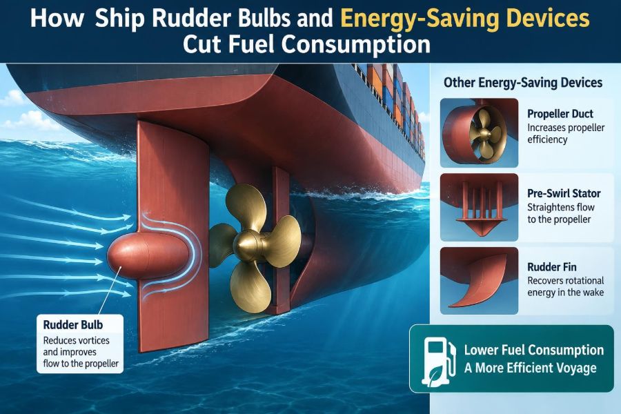

A vessel leaves dry dock with a freshly painted hull, a polished propeller, and a new bulb fitted ahead of the rudder. The change may look small compared with the size of the ship, yet it sits in one of the most energetic parts of the wake: directly behind the propeller.
At sea, fuel consumption is not determined by the main engine alone. It is the result of how efficiently the hull, propeller, rudder, and appendages work together to turn shaft power into useful forward motion.
For owners, operators, and engineers, even a modest reduction in resistance or propeller loss can matter over long trading periods. For students, these devices offer a practical lesson in applied fluid mechanics: flow that is already rotating, uneven, and turbulent can sometimes be recovered rather than wasted.
Rudder bulbs and related energy-saving devices are therefore not “bolt-on fuel savers” in a simple sense. Their value depends on vessel geometry, operating condition, propeller characteristics, installation quality, and careful verification after the modification. ⚓
⚓ 1. The fuel-efficiency problem around a propeller
A propeller produces thrust by accelerating water aft. Ideally, most of the energy delivered to the water would become a useful pressure difference that pushes the ship ahead.
In reality, the propeller slipstream also contains rotational motion, non-uniform velocities, turbulence, and losses associated with tip vortices and hub vortices. The rudder must then operate in this highly disturbed flow.
An energy-saving device aims to reduce a particular loss mechanism or improve the interaction between components. It does not create energy; it helps the propulsion system waste less of the energy already supplied by the engine.
🌊 2. Why the wake is not uniform
Water approaching a propeller is affected by the hull boundary layer, the ship’s stern shape, appendages, and the vessel’s draft and trim. The resulting wake field varies in speed and direction across the propeller disc.
Near the upper region of a conventional single-screw ship’s propeller, inflow may be slower because of the hull boundary layer. Other areas may receive faster or more angled flow.
This non-uniformity makes propeller design and rudder design an interaction problem. A device that works well in an ideal, uniform flow may perform differently behind an actual ship hull.
🌀 3. Understanding rotational energy loss
As a propeller turns, it imparts not only axial momentum but also a tangential velocity component to the water. This rotating slipstream is often called swirl.
Swirl represents kinetic energy that is not directly contributing to forward thrust. Some downstream devices are designed to straighten or recover part of this rotational flow.
The strongest organized vortex often appears near the propeller hub. This hub vortex is an important reason why bulbs, caps, and fins are commonly installed near the propeller axis.
🧭 4. The rudder’s dual role
The rudder is primarily a steering surface. When angled, it generates a hydrodynamic side force that turns the vessel, while its drag and lift characteristics influence manoeuvring and speed.
Behind the propeller, however, the rudder also encounters accelerated flow. Its profile, thickness, leading edge, gap to the propeller, and alignment can affect both resistance and propulsion efficiency.
A well-designed rudder arrangement must balance course-keeping, manoeuvrability, cavitation behaviour, structural strength, and propulsive performance. Improving one characteristic must not compromise another.
🔵 5. What is a rudder bulb?
A rudder bulb is a streamlined body fitted near the leading edge of the rudder, usually on or close to the propeller shaft centreline. It is positioned in the region affected by the propeller hub vortex.
It may be integrated into a full-spade rudder, attached to a rudder horn arrangement, or shaped as part of a specialized rudder profile. The exact geometry differs among designers and vessel types.
The bulb is sometimes referred to in industry as a Costa bulb, although that name is associated with a particular concept and should not be used as a generic performance guarantee.
🎯 6. How a rudder bulb can recover energy
The bulb changes the flow in the hub region. By providing a streamlined body in a low-pressure, vortical zone, it can reduce the intensity of the hub vortex and guide flow more smoothly onto the rudder.
Its shape may also produce a beneficial interaction with the propeller slipstream. The aim is to reduce rotational losses and improve the effective use of the flow leaving the propeller.
The device is effective only when its geometry matches the propeller, rudder, and local wake. An incorrectly sized or positioned bulb can add drag, disturb inflow, or worsen cavitation instead of delivering a benefit.
📐 7. Geometry matters more than appearance
A bulb that looks like a simple fairing is actually a hydrodynamic component. Important variables include its length, diameter, cross-sectional shape, nose radius, tail shape, and its distance from the propeller hub.
Its vertical and longitudinal location determine which parts of the slipstream it affects. Small positional changes can alter pressure distribution, vortex behaviour, and the loading experienced by the rudder.
Designers normally use model testing, computational fluid dynamics, or both to assess candidate shapes. Full-scale operating data is then valuable because real sea conditions and hull roughness cannot be reproduced perfectly in every prediction.
🛠️ 8. Integration with different rudder types
Rudder bulbs are most commonly considered for single-screw vessels with a rudder located immediately aft of the propeller. The practical arrangement depends strongly on whether the vessel has a full-spade, semi-balanced, flap, or horn rudder.
A full-spade rudder offers a continuous surface but requires careful attention to stock loads and structural arrangement. A horn rudder has different constraints around the horn, pintle region, and clearance envelope.
- Full-spade rudders: can allow an integrated centreline feature, subject to strength and steering-gear considerations.
- Horn rudders: may need a geometry that works around the rudder horn and support structure.
- High-lift rudders: require special review because added forms can influence gap flow and lift behaviour.
⚙️ 9. The propeller-rudder interaction
A propeller and rudder should not be evaluated as isolated components. The propeller changes the flow received by the rudder, while the rudder influences pressure recovery and the flow environment behind the propeller.
The clearance between propeller and rudder is particularly important. Too little clearance can increase unsteady pressure effects, while too much may reduce the ability of the rudder system to interact beneficially with the slipstream.
Engineers consider the entire stern propulsion package: hull form, shaft line, propeller, boss, rudder, and energy-saving appendages. This systems view is essential.
🧢 10. Propeller boss cap fins
A propeller boss cap fin, often abbreviated as PBCF, is fitted to the propeller boss cap. Its fins are arranged to counteract rotational flow near the hub.
Unlike a fixed rudder bulb, a boss cap fin rotates with the propeller. It is intended to reduce hub-vortex losses by modifying the flow immediately as it leaves the propeller hub.
The fin arrangement must be matched to propeller rotation direction, blade geometry, and hub shape. Poor matching can create undesirable loads, drag, or vibration.
🌀 11. Pre-swirl fins and stators
Pre-swirl devices are fitted ahead of the propeller. They intentionally give the incoming water a rotational component opposite to the rotational component created by the propeller.
If designed correctly, the propeller needs to impart less net rotational energy to the water. This can improve propulsive efficiency by reducing downstream swirl.
Pre-swirl fins also alter the local wake delivered to the propeller. Their potential benefit must therefore be assessed alongside cavitation margin, pressure pulses, and structural loading at the stern.
🛡️ 12. Wake-equalizing ducts
A duct installed ahead of the propeller can condition the wake flow. It is often called a wake-equalizing duct because one objective is to make inflow to the propeller more uniform.
Many designs use an asymmetric or partial ring rather than a complete circular nozzle. This arrangement can target regions of slower hull wake while avoiding unnecessary resistance elsewhere.
The duct may also produce useful lift-like forces or alter flow direction near the stern. Its performance depends on hull shape, loading condition, and operating speed.
🪽 13. Post-swirl fins and rudder fins
Post-swirl fins are placed aft of the propeller, commonly on the rudder or in the rudder region. Their purpose is to recover part of the slipstream’s rotational energy.
They act somewhat like fixed guide vanes, redirecting rotating flow toward a more axial direction. Because they are in the propeller wake, unsteady forces and fatigue considerations are important.
Rudder fins can be combined with a bulb concept, but the combined arrangement must be engineered as one system. Adding multiple devices without integrated analysis can produce interference rather than cumulative savings.
💨 14. Air lubrication is a different approach
Air lubrication systems reduce frictional resistance along parts of the hull by supplying air beneath the vessel. Their operating principle is different from a rudder bulb or propeller-flow device.
Instead of recovering rotational energy at the stern, air lubrication attempts to change the shear conditions between the hull and water. Its effectiveness can depend on hull form, draft, sea state, air distribution, and the power used by compressors or blowers.
This distinction is useful: all energy-saving technologies should be assessed by their net energy effect, including the energy required to operate supporting equipment.
📊 15. Comparing major device families
| Device family | Typical location | Main hydrodynamic purpose | Key design concern |
|---|---|---|---|
| Rudder bulb | At or near rudder leading edge | Modify hub-vortex and stern flow | Matching bulb geometry to propeller and rudder |
| Boss cap fins | On rotating propeller boss cap | Reduce hub-vortex rotational loss | Compatibility with propeller geometry and balance |
| Pre-swirl fins | Forward of propeller | Condition inflow and reduce net swirl | Cavitation, structural loads, wake interaction |
| Wake-equalizing duct | Forward of propeller | Improve wake distribution | Hull-specific design and added resistance |
| Post-swirl fins | Aft of propeller | Straighten rotational slipstream | Vibration and unsteady loading |
No row in this table is automatically superior. The best choice depends on the vessel’s baseline condition and the loss mechanism that dominates its stern flow.
🔍 16. Start with a baseline assessment
Before selecting a retrofit, engineers need a credible picture of current performance. This includes speed, shaft power, propeller revolutions, draft, trim, weather effects, hull condition, and operational profile.
A single voyage comparison is rarely enough because wind, waves, current, displacement, and fouling can mask small changes. Consistent data collection is more useful than isolated observations.
Relevant questions include:
- Is the vessel usually operating near design draft or across a wide range of drafts?
- Has hull or propeller roughness increased resistance over time?
- Are vibration, noise, cavitation, or steering issues already present?
- Does the vessel spend most time at one service speed or many different speeds?
🧪 17. Model tests and CFD in design
Model basin testing remains valuable for examining resistance, propulsion, manoeuvring, and wake interactions under controlled conditions. It can help compare alternative stern appendages before a full-scale investment.
Computational fluid dynamics, or CFD, provides detailed visualisation of pressure fields, streamlines, vortices, and wake distributions. It is especially useful for screening geometric variations.
Neither method removes engineering uncertainty. CFD results depend on mesh quality, turbulence modelling, boundary conditions, and validation, while model tests require careful scaling and interpretation.
📏 18. Full-scale verification after installation
The final test of a retrofit is full-scale operation. Performance monitoring should compare like-for-like conditions as far as practical and account for changes in displacement, weather, hull condition, and engine operation.
Engineers may examine shaft power at a given speed, fuel consumption, propeller revolutions, slip, vibration records, and steering behaviour. Trends over time are often more meaningful than one trial result.
If contractual verification is required, the measurement method and correction approach should be agreed before installation. Clear baselines prevent later disagreement about what caused an observed change.
🧱 19. Structural and class considerations
Any device attached to a rudder or stern structure must withstand hydrodynamic loads, vibration, impact risks, and cyclic fatigue. It must also be compatible with the rudder’s internal structure and welding details.
Changes to rudder geometry can affect stock torque, bearing loads, steering gear demands, and emergency steering performance. These aspects require formal engineering review.
Classification society requirements, flag-state obligations, and owner procedures may apply to the modification. Approval needs vary by vessel and alteration, so designers should address them early rather than treating them as a final paperwork step.
🔊 20. Cavitation and vibration risks
Cavitation occurs when local pressure falls sufficiently for vapour cavities to form and collapse. In the stern region, it can lead to noise, erosion, pressure fluctuations, and vibration.
An energy-saving device changes local pressure and velocity fields. This may improve or worsen cavitation depending on its shape and placement.
For that reason, a predicted power improvement alone is not enough. Designers must also consider propeller cavitation patterns, rudder cavitation, hull pressure pulses, and comfort or equipment limits aboard the vessel.
🧼 21. Fouling, damage, and maintenance
A smooth hydrodynamic surface is part of the device’s function. Marine growth, coating damage, corrosion, dents, and rough weld transitions can increase drag and alter the intended flow pattern.
Rudder bulbs and fins should be included in dry-dock inspection plans. Checks should cover coating condition, cracking, attachment details, erosion, and any evidence of contact damage.
Maintenance access also matters. A concept that performs well in a simulation but is difficult to inspect, repair, or coat may create lifecycle problems for the operator.
🧭 22. Effects on manoeuvring
Because these devices are close to the rudder, they can influence steering forces and flow separation at rudder angles. A modification should be checked for both ahead and astern operating conditions.
Manoeuvring behaviour matters particularly for vessels operating in confined ports, channels, offshore fields, or ice-prone areas. Predictable handling can be more valuable than a small theoretical efficiency gain.
Trials may include turning ability, zig-zag response, stopping behaviour, and course-keeping observations. Masters and pilots can provide important operational feedback after the retrofit.
📉 23. Why savings vary from ship to ship
Published claims about an energy-saving device should never be transferred directly from one vessel to another. Two ships of similar size can have different stern forms, propellers, drafts, operational speeds, and hull conditions.
The potential gain also depends on the baseline. A vessel with a poorly matched or heavily degraded stern system may have more improvement potential than a vessel already optimized for its service.
Hydrodynamic efficiency is vessel-specific. The proper question is not “Does this device save fuel?” but “Which loss does it address on this particular vessel, and what evidence supports the prediction?”
🧮 24. A practical selection workflow
A disciplined retrofit process reduces the risk of choosing equipment based only on appearance or marketing claims. It connects the proposed device to an identified technical problem.
- Collect reliable baseline operational and machinery data.
- Inspect hull, propeller, rudder, and appendage condition.
- Define the vessel’s normal draft, trim, speed, and route profile.
- Identify likely losses through analysis, measurement, and specialist review.
- Develop device options that fit structural and operational constraints.
- Assess hydrodynamics, cavitation, vibration, strength, and approvals together.
- Install with controlled fabrication and alignment procedures.
- Monitor performance over a meaningful operating period.
👷 25. What marine engineers should inspect
Engineers on board and ashore play a central role after installation. Their observations can reveal whether a device is performing as intended or creating unexpected side effects.
Useful inspection and monitoring points
- Changes in shaft power, revolutions, and fuel rate at comparable operating points.
- New vibration, noise, steering effort, or autopilot activity.
- Coating wear, cavitation erosion, cracks, or loose fittings at dry dock.
- Propeller and rudder clearances following any repair work.
- Differences between ballast and loaded-condition behaviour.
Good records turn operational experience into usable engineering evidence. They also help distinguish a device-related change from ordinary variations caused by weather, maintenance, or loading.
🎓 26. Key concepts for students and professionals
Rudder bulbs and energy-saving devices bring several marine engineering subjects together: resistance, propulsion, fluid dynamics, structures, vibration, maintenance, and ship operations.
The most important lesson is that a ship is a coupled hydrodynamic system. Improving the propeller alone, or the rudder alone, may miss the interaction that determines actual propulsive performance.
Professionals should be comfortable reading wake plots, thrust and torque data, cavitation observations, and sea-trial trends. Students should connect these practical outputs to the underlying ideas of momentum, pressure, circulation, and energy loss.
✅ 27. The core principle: recover losses without creating larger ones
A rudder bulb, duct, fin, or boss-cap device can reduce fuel consumption when it improves the way water flows through the stern propulsion system. Its purpose is usually to reduce swirl, improve wake quality, recover pressure, or lower resistance.
But every appendage also has drag, structural, operational, and maintenance consequences. The best design is not the one with the most hardware; it is the one that produces the best net result for a specific ship and service profile.
Effective energy saving comes from understanding the vessel’s real flow losses and designing the whole hull-propeller-rudder system to manage them intelligently. 🚢⚙️🌊