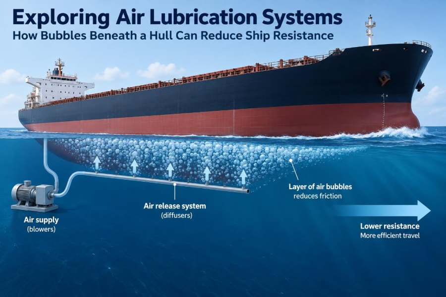

A ship’s hull may look smooth from the quay, but the water beneath it is doing demanding work. As the vessel moves forward, seawater rubs against thousands of square metres of wetted steel, continuously consuming propulsion power.
For a crew focused on safe navigation and reliable machinery, that resistance can seem unavoidable. Yet one approach tries to change the water immediately next to the hull: it deliberately introduces air.
Air lubrication systems send bubbles, air layers, or air cavities beneath selected parts of a ship. The aim is not to make the ship float higher in any dramatic sense. It is to reduce frictional resistance where the hull meets water.
That simple idea connects fluid mechanics, hull design, compressors, controls, maintenance, and emissions reduction. It also comes with operating limits that engineers need to understand before treating it as a universal solution.
🌊 Why Hull Resistance Matters
A moving ship must overcome several forms of resistance. Frictional resistance comes from the shearing action between water and the hull surface; wave-making resistance comes from creating waves; appendages, wind, fouling, and shallow-water effects can add further losses.
For many full-form commercial vessels operating at moderate speed, skin friction is a major share of the total resistance. Because the underwater hull area is so large, even a modest reduction in wall friction can reduce the propulsive power needed to maintain speed.
Less required shaft power can mean lower fuel use or, on vessels with alternative fuels, lower energy consumption. The exact outcome depends on the ship, route, draft, weather, loading condition, machinery arrangement, and the power needed to generate the air.
🧭 The Core Idea Behind Air Lubrication
Air lubrication places gas between the moving hull and the surrounding water. Air has a far lower viscosity than water, so an air-rich layer near the hull can offer less shear resistance than a fully wetted boundary layer.
A useful analogy is rubbing a hand across a wet tabletop versus allowing a thin layer of soapy water or air to alter the contact. The comparison is imperfect, because a ship operates in turbulent flow rather than simple sliding contact, but it captures the goal: change the interface to reduce drag.
The system does not eliminate contact with water across the whole ship. Instead, it seeks to create and sustain favorable air coverage over selected flat or gently curved regions of the bottom.
⚙️ Frictional Resistance and the Boundary Layer
Water next to a stationary hull has nearly zero velocity relative to that hull. Moving away from the surface, water velocity increases until it approaches the free-stream velocity. This region of changing velocity is the boundary layer.
On most ship hulls, much of the boundary layer is turbulent. Turbulence mixes momentum vigorously, increasing the shear stress at the wall and therefore increasing frictional drag.
When bubbles or an air layer occupy part of the near-wall region, the local flow structure changes. The potential benefit arises from reduced effective contact and altered shear behavior, but the details are sensitive to bubble size, void fraction, pressure, hull geometry, and flow speed.
🫧 What “Air Lubrication” Can Mean
The term covers several related but distinct approaches. Treating them as interchangeable can lead to poor design decisions because each requires different hardware and behaves differently under the hull.
| Approach | Basic mechanism | Typical engineering challenge |
|---|---|---|
| Microbubble lubrication | Injects many small bubbles into the boundary layer | Maintaining useful bubble distribution downstream |
| Air-layer lubrication | Creates a more continuous air film or layer under a flat bottom region | Keeping the layer stable against flow and pressure changes |
| Air-cavity lubrication | Uses recessed hull features to retain larger air pockets | Designing cavities that hold air without unacceptable flow losses |
Some systems sit between these categories in practice. A vessel may release air through slots, porous panels, or discrete injectors, and the resulting flow can contain bubbles, streaks, patches, and locally continuous layers.
🔬 Microbubbles: Small Bubbles, Complex Flow
Microbubble systems inject fine bubbles from distributors fitted in the hull bottom. The bubbles are carried aft by the external flow, creating an aerated region along the wetted surface.
Small bubbles can follow the near-wall flow more readily than large bubbles, but they are not automatically better. They may dissolve, coalesce into larger bubbles, migrate away from the target region, or disperse unevenly in turbulence.
The injector arrangement must therefore suit the ship’s flow pattern. A pattern that appears uniform at the injection point may become patchy after passing stiffeners, hull curvature, sea chests, bilge keels, or other disturbances.
🛶 Air Layers and Continuous Coverage
Air-layer concepts aim for a more coherent sheet of air beneath the hull. This can offer a larger local reduction in water-to-hull contact than a sparse bubbly flow, especially over relatively flat bottom sections.
Maintaining continuity is difficult. Hydrostatic pressure increases with draft, while the fast-moving external flow tends to sweep air aft and can break the layer into streaks or bubbles.
Ship motions matter as well. Pitch, roll, heave, trim changes, and operation in waves can alter local pressure and flow direction. A system that works efficiently in calm, steady trial conditions may behave differently on a working route.
🧱 Air Cavities and Hull Recesses
An air cavity is a shaped recess in the hull intended to trap or stabilize a gas pocket. Rather than continuously covering an open flat surface, the geometry helps retain the air in a defined region.
These arrangements demand careful integration with structural design, fabrication, coatings, inspection access, and hydrodynamic performance. The cavity itself must not introduce losses that cancel the expected benefit.
The concept illustrates a broader rule: air lubrication is not merely an auxiliary machine installation. In some forms, it is a hull-form and naval-architecture decision made early in the design process.
📍 Where Air Is Introduced
Injection points are commonly placed forward of the areas intended for coverage, often on the flat bottom where the flow can carry air aft. The best location is vessel-specific rather than a fixed distance from the bow.
Engineers consider local pressure, expected streamline paths, hull curvature, appendages, draft range, and the risk of air entering places where it is unwanted. The aim is to maximize useful coverage while minimizing compressor power and operational complications.
Computational fluid dynamics, model testing, full-scale measurements, and operational feedback can all contribute. Each method has limitations, so a reliable design usually relies on more than one form of evidence.
💨 The Air Supply System
Below the waterline, air must be supplied at a pressure high enough to overcome local seawater pressure and losses in pipes, valves, and distributors. Compressors or blowers therefore become part of the energy balance.
A practical installation may include air compressors, dryers where required, receivers, filters, control valves, distribution piping, non-return devices, instrumentation, and local isolation arrangements. The exact configuration depends on the selected technology and class requirements.
Air quality deserves attention. Oil, water, scale, or debris in the supply can affect valves and small openings. Poorly maintained distribution hardware can turn a carefully designed system into an uneven and inefficient one.
⚡ Net Energy Savings, Not Gross Drag Reduction
The relevant performance question is not simply whether air reduces hull friction. It is whether the net energy balance is favorable after accounting for compressor or blower power.
If a system reduces required propeller power but consumes nearly as much electrical power to produce and distribute air, its operational value may be limited. Conversely, a modest friction reduction may still be worthwhile if the air plant is efficient and operates in a favorable condition.
Engineers should compare total power demand with the system on and off at comparable speed, draft, trim, weather, and sea state. A single observation without those controls can be misleading.
📊 Why Performance Varies Between Voyages
Air lubrication does not produce one fixed percentage saving. Performance can vary with hull condition, vessel speed, draft, trim, water temperature, salinity, wave conditions, and the stability of the air distribution.
For example, a deeply loaded vessel has higher pressure at the injection points than the same vessel in ballast. That changes the air-delivery requirement and may change how bubbles develop beneath the hull.
Weather also complicates comparison. Added resistance in waves, changing wind, and speed adjustments by the bridge can mask or exaggerate the apparent contribution of the system unless data are interpreted carefully.
🚢 Ships That May Be Suitable
Air lubrication is generally most attractive where frictional resistance is a significant part of the resistance budget and where the hull provides favorable areas for air coverage. Broad, relatively flat-bottomed vessels can offer useful installation opportunities.
Suitability must still be assessed case by case. A ship with complex bottom geometry, numerous appendages, frequent draft changes, or operational profiles dominated by low speed may not obtain the same value as another vessel of similar size.
- Tankers and bulk carriers may offer broad bottom areas, but their draft variation needs consideration.
- Container vessels can have high power demand, yet their hull flow and operating speed require careful analysis.
- Cruise ships and passenger vessels may value fuel savings and emission reductions, while also needing attention to noise, vibration, and service reliability.
- Inland and coastal vessels may face different constraints from shallow water, debris exposure, and variable operating profiles.
📐 Hull Form, Trim, and Wetted Area
The potential target is the wetted area, but not every square metre is equally useful. The local flow must carry air in a way that reduces friction rather than allowing it to escape quickly or collect in unfavorable regions.
Trim changes alter the pressure distribution and immersion of the hull. A stern-down condition, for instance, may change both the flow over an aft-covered region and the power needed to move air from forward injectors.
For this reason, air lubrication should be considered alongside trim optimization. The best trim for bare-hull resistance may not exactly match the best operating condition for a particular air distribution arrangement.
🧮 Measuring Whether the System Works
Full-scale verification requires disciplined data collection. Shaft power, speed through water, draft, trim, compressor power, weather, sea state, engine condition, and hull cleanliness all influence interpretation.
Speed over ground alone is not sufficient because current can distort the comparison. Speed through water is usually more relevant to hydrodynamic resistance, though sensor quality and calibration also matter.
A useful approach is to compare repeated operating points over time and analyze trends rather than declaring success from one short on/off test. The measurement plan should be established before commissioning, not improvised after the vessel enters service.
🖥️ Controls and Automation
Modern systems can adjust airflow according to speed, draft, loading condition, or selected operating mode. Automation can prevent wasteful operation when the expected benefit is low or when machinery limits make air supply undesirable.
Control logic should avoid chasing noisy signals. Rapidly changing valve positions may create unstable flow and unnecessary wear, so practical systems often use sensible limits, delays, and operating bands.
The bridge and engine-room teams also need clear status information: whether the system is available, how much electrical power it uses, whether airflow is balanced, and what alarms require attention.
🔧 Installation Challenges on Newbuildings
Newbuildings offer the best opportunity to integrate injectors, piping, machinery foundations, cable routes, access spaces, and structural details from the beginning. Early coordination prevents last-minute compromises around tank boundaries or equipment rooms.
Distribution panels must be protected during construction and accessible later for inspection. Weld distortion, coating quality, fairing, and the exact flushness of hull outlets can all affect external flow.
Naval architects, structural engineers, machinery designers, yard teams, class representatives, and the owner’s technical staff need aligned requirements. A hydrodynamically promising layout can be difficult to maintain if access has not been designed in.
🛠️ Retrofit Realities
Retrofitting an existing ship can be attractive, but it is more constrained than fitting the system on a newbuilding. The vessel may need dry-docking work for hull outlets, internal steel modifications, piping runs, electrical capacity, and machinery-space rearrangement.
Space and power availability are common constraints. A compressor installation that looks compact on a drawing still needs foundations, ventilation, drainage, service clearance, noise control, and safe access.
Before approving a retrofit, operators should examine the remaining service life, dry-docking schedule, route profile, expected maintenance burden, and whether the performance case remains credible across the ship’s normal drafts.
🧰 Maintenance of Injectors and Piping
Small air outlets are vulnerable to fouling, coating blockage, corrosion products, and mechanical damage. Uneven distribution may not always trigger an immediate alarm, yet it can gradually reduce performance.
Routine maintenance should include checks of compressor condition, filters, drains, valves, pressure readings, flow indications, non-return devices, and distribution zones. Underwater inspections and dry-dock inspections are useful opportunities to examine external components.
A maintenance record should connect defects with operating data. If one zone consistently needs more pressure or delivers less airflow, the cause may be a restriction, leak, damaged outlet, or control issue rather than a mysterious hydrodynamic change.
🧪 Biofouling and Hull Coatings
Air lubrication does not remove the need for effective antifouling protection. A rough or fouled hull raises frictional resistance and may reduce the relative or absolute benefit available from the air system.
Coating selection must also suit the injector arrangement. Coating application needs clear procedures so outlets are not accidentally sealed, partially blocked, or left with edges that disturb flow.
Think of hull cleaning and air lubrication as complementary measures. One reduces resistance caused by surface roughness; the other aims to alter the near-wall fluid environment. Neither fully substitutes for the other.
🔊 Noise, Vibration, and Comfort
Compressors, blowers, valves, and airflow can introduce noise and vibration. These effects may be manageable, but they should be considered in machinery-space design and, for passenger vessels, in accommodation comfort assessments.
Flexible connections, resilient mounts, silencers, suitable pipe supports, and careful routing can reduce transmitted vibration. Pulsating airflow can also affect piping behavior, so support design should not be treated as an afterthought.
Operational noise is not only a comfort issue. Unusual sound can help engineers identify a failing valve, air leak, bearing problem, or unstable compressor condition before a larger failure develops.
⚠️ Safety and Operational Boundaries
Air systems require normal machinery safety controls: pressure protection, isolation, electrical safeguards, machinery guarding, alarm management, and procedures for maintenance. The equipment should be included in the vessel’s planned-maintenance and emergency-response framework.
Air must not be allowed to interfere with sensors, intakes, propulsion equipment, or other underwater systems. The risk depends heavily on the particular hull and arrangement, which is why integration reviews are essential.
Crews also need a clear response to abnormal conditions. A loss of airflow is generally a performance issue rather than a navigational emergency, but a pipe failure, machinery fault, or unexpected alarm should have a defined and practiced procedure.
🌦️ Sea State and Real-World Operation
Calm-water hydrodynamics provide a useful baseline, but ships earn their living in changing seas. Wave-induced motions alter the local water pressure and can disrupt bubbles or air layers.
In rough conditions, added resistance may dominate the voyage power demand. An air lubrication system may still operate, but the net result can differ from smooth-water expectations, and operators may choose settings that prioritize reliability or electrical load management.
This does not make the technology ineffective. It means performance assessment must reflect the vessel’s actual trading pattern, not only idealized trial conditions.
🌱 Emissions and Energy-Management Context
Air lubrication is one tool in a broader efficiency strategy. Reducing hull resistance can lower the energy needed per voyage, which can support lower emissions when the vessel’s energy source produces greenhouse gases.
Its contribution should be evaluated alongside speed management, weather routing, propeller maintenance, hull cleaning, trim optimization, waste-heat recovery, shore power, and machinery improvements. The best package differs by vessel.
A system’s environmental value depends on its net power effect and operating use. Running inefficient compressors merely to claim a technology is installed would not deliver the intended outcome.
🧩 Integration With Propulsion Systems
When hull resistance falls, the propeller and main engine operate at a different point on their respective curves. This can affect shaft power, engine loading, controllable-pitch settings, generator demand, and sometimes the preferred operating speed.
Engineers should look beyond a single fuel-flow number. The auxiliary power consumed by compressors may be supplied by generators with their own loading characteristics, and those generators may operate less efficiently at some loads.
For vessels with hybrid or battery-supported electrical systems, the timing of compressor demand can matter. Control strategies may need to account for available electrical power as well as hydrodynamic benefit.
❌ Common Misunderstandings
One misconception is that the air makes a ship significantly buoyant. In normal air-lubrication operation, the purpose is drag reduction at the hull surface, not a meaningful reduction in displacement.
Another is that more air must always be better. Excess flow can waste energy, escape without covering the target area, or create an unfavorable distribution. The goal is efficient, controlled air delivery.
A third mistake is assuming one vessel’s result can be copied directly to another. Similar ships can differ in hull form, routes, drafts, machinery, and maintenance condition enough to change the business and engineering case.
🧠 A Practical Evaluation Checklist
Before selecting an air lubrication system, a project team should define what it needs to know and how it will verify it. A vendor proposal is only one input to that decision.
- Characterize normal speed, draft, trim, route, and weather profile.
- Estimate the frictional-resistance opportunity for the actual hull.
- Identify available electrical power, machinery space, and dry-dock constraints.
- Assess air distribution, access for inspection, and likely fouling exposure.
- Calculate net, not gross, energy benefit across representative conditions.
- Plan commissioning tests and long-term performance monitoring.
- Include crew training, spares, and maintenance responsibility in the lifecycle plan.
The objective is not to find a universally favorable answer. It is to establish whether the technology fits a particular ship and how its value can be protected in service.
📚 Skills Marine Engineers Need
Air lubrication sits at the intersection of fluid mechanics and shipboard engineering. Marine engineers benefit from understanding compressors, pneumatic systems, electrical load, automation, maintenance planning, and machinery troubleshooting.
Naval architects and performance analysts need to understand boundary layers, resistance components, hull pressure fields, and data uncertainty. Neither discipline can assess the complete system in isolation.
For students, this is a useful reminder that many efficiency technologies are systems problems. A promising physical principle only becomes a practical solution when equipment, crew procedures, vessel operations, and measurement methods work together.
🔭 Where Development May Continue
Future improvements may come from better hull-integrated distributors, more efficient air machinery, adaptive control, improved sensing of air coverage, and design methods that connect simulations with full-scale operating data.
There is also room to improve how performance is monitored. Detecting whether air is reaching the intended hull area remains more difficult than measuring compressor power, so indirect indicators must be interpreted with care.
Progress will likely be incremental rather than magical. The most valuable advances will be those that improve reliable net savings, reduce maintenance demands, and make performance more predictable across real operating conditions.
🧭 The Core Takeaway: Manage the Interface
Air lubrication works by managing the interface between a moving hull and seawater. By introducing air into carefully selected near-hull flow regions, it can reduce part of the frictional resistance that demands propulsive power.
Its success depends on the whole chain: suitable hull geometry, effective injection, stable downstream coverage, efficient compressors, sound controls, clean outlets, realistic operating conditions, and honest net-energy assessment.
The central lesson is broader than one technology. Marine efficiency gains are rarely created by a single component alone; they emerge when hydrodynamics, machinery, operation, and maintenance are designed to support the same objective.
Bubbles beneath a hull can reduce resistance, but only a well-integrated and well-operated system turns that physical possibility into dependable shipboard efficiency. 🚢🫧🌊