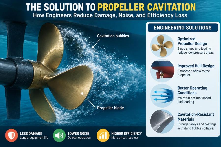

A vessel can leave the berth with a clean hull, a well-maintained engine, and a propeller that looks perfectly sound. Yet as power rises, a faint vibration may appear through the stern, followed by a harsh underwater roar and a loss of expected speed.
That combination often points to propeller cavitation. It is easy to mistake it for a normal consequence of hard working conditions, especially on fast craft or heavily loaded ships. But uncontrolled cavitation can erode metal, disturb flow into the propeller, create unacceptable noise, and turn engine power into wasted energy.
For marine engineers, the challenge is not to eliminate every vapour bubble in every operating condition. Some cavitation is difficult to avoid. The practical goal is to control where it occurs, how violently it collapses, and whether the propeller can still deliver thrust safely and efficiently.
The solution therefore begins long before a vessel enters dry dock. It involves hydrodynamics, hull form, machinery operation, propeller geometry, measurement, and careful maintenance.
🌊 What Propeller Cavitation Actually Is
Cavitation occurs when local pressure in water falls below the water’s vapour pressure. Instead of remaining liquid, the water forms vapour-filled cavities or bubbles. When those cavities move into a higher-pressure region, they collapse.
Near a propeller, this process is driven by the pressure difference created as each blade produces thrust. The suction side of a blade has lower pressure; if that pressure becomes low enough, vapour cavities can form there.
The destructive part is usually not the bubble’s creation but its collapse. A collapse close to a blade or hull surface can produce a highly localised pressure pulse, much like countless tiny impacts against the material.
⚙️ Why a Propeller Needs Low Pressure to Make Thrust
A propeller blade works like a rotating hydrofoil. Its shape and angle create a pressure difference between its two sides, accelerating water aft and generating forward thrust.
This means low pressure is not automatically a design fault. The problem begins when the required pressure reduction is too severe for the available water pressure at that location.
Engineers therefore balance two competing needs: enough blade loading to move the vessel, and sufficiently moderate suction-side pressure to avoid aggressive vapour formation. A propeller with too little area, for example, may need to load each blade excessively.
🫧 The Main Types of Cavitation
Different cavitation patterns indicate different flow conditions. Identifying the pattern matters because the corrective action for one form may not help another.
| Type | Typical appearance | Common concern |
|---|---|---|
| Sheet cavitation | A vapour sheet over part of the suction side | Efficiency loss, collapse near the trailing region |
| Tip-vortex cavitation | A spiral vortex from the blade tip | Noise and vibration; often visible in clear water |
| Cloud cavitation | Detached, unsteady vapour clouds | Strong pressure pulses and erosion risk |
| Root cavitation | Cavitation near the blade root | May be linked to hub flow or uneven wake |
| Bubble cavitation | Scattered small bubbles | Can indicate disturbed inflow or local roughness |
These patterns can coexist. A propeller operating behind a full hull may experience a different cavitation pattern on each blade as it passes through the vessel’s non-uniform wake.
📉 Why Cavitation Reduces Propulsive Efficiency
When a blade surface is covered by a vapour cavity, the intended pressure distribution changes. Part of the blade may no longer transfer energy to the water in the way the designer intended.
The result can be reduced thrust for a given shaft power, unstable torque, and a change in propeller slip. The engine may appear to be delivering power normally while the vessel gains less speed than expected.
Not every cavity causes a dramatic efficiency penalty. However, extensive or unstable cavitation generally makes propulsion less predictable and often requires more power to maintain service speed.
🔊 Why Cavitation Creates Noise and Vibration
Collapsing cavities generate pressure fluctuations in the surrounding water. Those fluctuations can excite the propeller shaft, stern structure, hull plating, and onboard equipment.
Passengers may notice vibration, while crew may hear a rumbling, crackling, or pounding sound near the stern. Underwater noise is also a serious concern for research vessels, naval platforms, and ships operating in environmentally sensitive areas.
The issue is especially significant when blade-passing pressure pulses coincide with structural natural frequencies. In that case, a relatively small hydrodynamic excitation can produce a much more noticeable vibration response.
🔨 How Cavitation Erodes Propeller Blades
Cavitation erosion is a material-damage mechanism caused by repeated cavity collapse close to a solid surface. Over time, the surface develops a frosted appearance, pits, and eventually deeper material loss.
Damage often appears near the trailing edge, blade tip, or areas where a cavity closes. The exact location is useful evidence: it can help a specialist infer the cavity pattern and probable flow problem.
Bronze and nickel-aluminium-bronze propellers resist seawater corrosion well, but no common propeller material is immune to sustained aggressive collapse. Welding or filling pits without correcting the cause may only delay the next repair.
🧭 The Role of Depth and Ambient Pressure
Water pressure increases with depth. A deeply submerged propeller has a higher ambient pressure around it, giving more margin before local blade pressure reaches vapour pressure.
This is why shallow draft, high-speed craft are especially susceptible. As the stern rises at speed, the propeller may operate closer to the free surface, where lower static pressure and air ingestion make the flow more difficult.
Sea state also matters. In following waves or during pitching, the propeller’s immersion can change rapidly, producing intermittent cavitation even if steady-water trials appeared acceptable.
🌬️ Ventilation Is Not the Same as Cavitation
Ventilation occurs when air or exhaust gas is drawn into the propeller flow. Cavitation is the formation of water vapour because pressure has fallen sufficiently low. Both can reduce thrust and cause racing, but they are not the same phenomenon.
A ventilating propeller may suddenly lose grip when a surface-connected air path reaches the blades. This is common with poor immersion, sharp manoeuvres, damaged anti-ventilation arrangements, or a stern that lifts excessively.
Confusing the two can lead to the wrong remedy. Increasing blade area may help a loading-related cavitation problem, whereas improving immersion or altering appendage geometry may be more relevant for ventilation.
🚢 Hull Wake: The Propeller’s Incoming Flow
A propeller does not usually receive smooth, uniform water. Behind the hull, the wake is slowed and redirected by the vessel’s boundary layer, stern shape, shafts, brackets, bilge keels, and other appendages.
As a blade rotates through a non-uniform wake, its angle of attack and load change cyclically. The upper blade may encounter slower water near the hull, then move into faster flow lower in the disc. That variation can trigger periodic cavitation and pressure pulses.
A good propeller design must therefore be matched to the vessel’s wake field, not selected from diameter and engine power alone.
📐 Blade Area and Disc Loading
Disc loading is the thrust demanded per unit area of the propeller disc. High disc loading tends to require stronger pressure differences around the blades, increasing cavitation risk.
Increasing diameter is often an effective way to reduce loading, provided draft, hull clearance, shaft arrangement, and tip-speed limits allow it. Increasing blade area can also spread the load, although extra area brings frictional drag and may alter efficiency.
The best solution is rarely “the largest possible propeller.” It is a balanced design that delivers the required thrust within geometric, structural, acoustic, and operational constraints.
🌀 Pitch, RPM, and Blade Loading
Pitch is the theoretical forward distance a propeller would advance in one revolution through a solid material. In water, actual advance is lower because the propeller accelerates the flow and experiences slip.
For a fixed vessel speed, raising RPM increases blade passage frequency and can raise local loading if the system demands more thrust. Excessive RPM also increases tip speed, a major cavitation driver.
Changing pitch can redistribute loading, but it is not a universal cure. A pitch change that helps at one speed may worsen engine matching, acceleration, or efficiency at another.
🏎️ Why Tip Speed Matters So Much
The outer part of a blade travels fastest. It also carries substantial load, so the blade tip is a frequent site of low pressure and vortex formation.
High tip speed encourages tip-vortex cavitation and can increase radiated noise. Designers may reduce RPM and use a larger diameter propeller where space permits, or use gearing to let the engine run efficiently while the propeller turns more slowly.
On a fast vessel, physical limits may prevent a large, slow-turning propeller. The engineering task then becomes managing a more demanding compromise rather than assuming cavitation can be designed away entirely.
🛠️ Blade Geometry That Controls Cavitation
Propeller geometry controls how lift is produced and where low-pressure regions develop. Useful design variables include chord distribution, skew, rake, thickness, camber, section shape, and pitch distribution from root to tip.
Modern propeller sections are shaped to manage pressure peaks more gently. Instead of concentrating suction near the leading edge, a designer may distribute the load along the chord, reducing the tendency for a large cavity to form abruptly.
Thickness cannot simply be minimised. Blades must withstand hydrodynamic loads, fatigue, impact risk, and manufacturing constraints. Structural reliability remains part of cavitation control.
📏 Skew and Its Practical Benefits
Skew describes how far the blade planform sweeps around the hub. Highly skewed propellers can enter and leave an uneven wake more gradually, helping to reduce sudden loading changes.
That may lower pressure pulses and improve comfort on vessels where stern vibration is a problem. Skew can be particularly valuable behind hulls with strongly non-uniform wake fields.
However, skewed blades are not automatically superior. They can be more flexible, more complex to manufacture and repair, and must be designed with appropriate strength and fatigue behaviour.
🧱 Surface Condition Is a Hydrodynamic Issue
Marine growth, paint defects, corrosion, rough repairs, and leading-edge damage disturb the boundary layer over a blade. Those defects can create local pressure disturbances and promote earlier cavitation.
A small nick may look cosmetic but can become a stress raiser and a flow disturbance. The resulting problem is not always dramatic, yet it can contribute to noise, imbalance, and reduced efficiency.
Proper finishing after repair matters. The blade profile, edge radius, and surface smoothness should be restored as closely as practical to the intended geometry rather than merely made visually acceptable.
⚖️ Balance, Alignment, and Mechanical Health
Cavitation is primarily a hydrodynamic phenomenon, but mechanical defects can magnify its symptoms. A bent blade, uneven pitch, poor static balance, shaft misalignment, or worn bearing can all increase vibration.
These defects may also change the effective blade loading. If one blade carries more load than the others, it can cavitate more intensely and create a once-per-revolution vibration signature.
A sound investigation separates cause from consequence. Replacing a damaged propeller without checking alignment, shaft condition, and bearing clearances may leave part of the problem unresolved.
🔍 Recognising the Warning Signs at Sea
Operators should watch for changes rather than rely on a single symptom. Cavitation may be suspected when vibration, noise, fuel use, shaft torque behaviour, or achievable speed changes at a familiar loading condition.
- Unusual stern vibration at a specific RPM range
- Engine racing or sudden loss of thrust during manoeuvres
- Reduced speed at normal power after fouling or damage
- Repeated pitting near blade tips or trailing edges
- Noise that rises sharply after a particular speed threshold
None of these signs proves cavitation by itself. Hull fouling, machinery faults, poor engine performance, and ventilation can produce overlapping symptoms.
📊 Measuring the Problem Instead of Guessing
A useful diagnosis combines operational records with inspection and, where justified, specialised measurement. Shaft RPM, power, vessel speed, draft, trim, sea condition, and vibration data provide a valuable first picture.
Underwater acoustic measurements can indicate changes in cavitation noise. Hull pressure sensors and accelerometers can help identify whether blade-passing excitation is reaching the structure.
For major design work, model testing in a cavitation tunnel or computational fluid dynamics analysis may be used. Both have limitations: scaled models and numerical simulations require careful interpretation, especially when wake quality and unsteady flow are involved.
🧪 Cavitation Tunnels and Model Testing
A cavitation tunnel allows a model propeller to run in controlled water flow and pressure. Engineers can observe cavity patterns, measure thrust and torque, and assess pressure fluctuations under selected conditions.
The method is particularly valuable when comparing design alternatives. A change in skew, blade section, or pitch distribution can be evaluated before committing to a full-size propeller.
Results must be scaled thoughtfully. Full-scale surface roughness, sea conditions, hull wake, and manufacturing variation can differ from model conditions, so tunnel work supports judgement rather than replacing it.
💻 What CFD Can—and Cannot—Show
Computational fluid dynamics, or CFD, models fluid flow numerically. It can reveal pressure distributions, wake non-uniformity, vortex structures, and likely cavitation regions early in the design process.
CFD is valuable for comparing options and understanding why a design behaves as it does. It can also explore hull-propeller interaction without building every alternative as a physical model.
Its predictions depend on mesh quality, turbulence modelling, boundary conditions, and the cavitation model selected. A visually convincing result is not enough; it should be checked against measurements and practical operating knowledge.
🧰 Repairing Cavitation Damage Correctly
When erosion is found, the first question is whether the blade remains structurally acceptable. A qualified propeller repair facility can assess thickness, cracks, pitch, balance, and whether welding is appropriate for the alloy and damage location.
Repair commonly involves removing damaged material, restoring profile by approved welding or metal build-up where suitable, fairing the surface, and checking pitch and balance. Heat input and weld procedure matter because poor repair can affect material properties or introduce residual stress.
After repair, investigate the operating cause. Otherwise, the restored region may become the first place to erode again.
🧽 Fouling Control as a Cavitation Strategy
Fouling increases hull resistance, so the propulsion system must deliver more thrust to maintain speed. That higher demand can push an already marginal propeller into more severe cavitation.
Fouling on the propeller itself is even more direct: it raises roughness, disturbs blade flow, and reduces hydraulic efficiency. Regular underwater inspection is particularly useful for vessels that spend long periods idle in warm, biologically active waters.
Cleaning should be performed with methods suitable for the coating and environmental rules of the operating area. Aggressive cleaning that damages a blade finish can trade one performance problem for another.
⚓ Controllable-Pitch Propellers and Operating Flexibility
A controllable-pitch propeller can vary blade pitch while the shaft continues rotating. This gives useful control of thrust and can help keep the engine in a suitable operating range during changing load conditions.
It does not eliminate cavitation. At inappropriate pitch and RPM combinations, a controllable-pitch propeller can still experience high blade loading, poor inflow, or ventilation.
Its advantage is flexibility: operators may be able to select a combination that avoids a troublesome RPM or loading condition more easily than with a fixed-pitch arrangement.
🔄 Ducted, Contra-Rotating, and Alternative Concepts
Ducted propellers can improve low-speed thrust in some applications by using a nozzle to recover and direct flow. They are common where bollard pull or low-speed towing performance matters, but the duct adds drag at higher speeds.
Contra-rotating propellers can recover some rotational energy left in the slipstream, although their machinery and control arrangements are more complex. Podded drives, waterjets, and surface-piercing systems each bring different cavitation and ventilation behaviours.
No propulsion concept is universally best. Vessel speed, draft, mission profile, noise requirement, maintenance capability, and installation space determine whether an alternative is worthwhile.
🚦 Operating Practices That Reduce Cavitation
Operators often have meaningful control over cavitation severity. Avoiding prolonged operation at a known vibration-prone RPM can reduce pressure pulses and fatigue exposure.
Maintaining adequate draft and avoiding excessive stern trim helps preserve immersion. During rough weather, reducing speed may prevent repeated propeller emergence and violent re-entry.
- Record speed, RPM, power, draft, and trim when symptoms occur.
- Use manufacturer-approved operating limits for pitch and shaft speed.
- Investigate abrupt performance changes promptly.
- Do not treat persistent vibration as a normal condition.
These practices cannot correct a fundamentally unsuitable propeller, but they can limit damage while the underlying cause is assessed.
❌ Common “Fixes” That Miss the Real Cause
Simply polishing a propeller may help if roughness is the trigger, but it will not correct excessive disc loading or a severely uneven wake. Likewise, reducing RPM may reduce symptoms while leaving the vessel unable to meet its required duty.
Adding blade area without analysis can increase drag and alter engine matching. Changing pitch by trial and error may move the problem to another speed range or overload the engine.
The most costly mistake is treating cavitation as only a propeller problem. The hull wake, vessel trim, appendages, propulsion train, and operational profile all belong in the diagnosis.
🧩 A Practical Investigation Sequence
A disciplined sequence prevents expensive, isolated modifications. Start by defining the operating condition in which the problem occurs, then compare it with known baseline performance.
- Confirm loading, draft, trim, speed, RPM, and sea condition.
- Inspect the hull, appendages, propeller, and shaftline for defects or fouling.
- Review vibration, power, and speed trends where records exist.
- Distinguish likely cavitation from ventilation and mechanical faults.
- Use specialist hydrodynamic analysis when geometry or wake changes are proposed.
- Verify the result after repair or modification under comparable conditions.
This approach turns a vague complaint—“the ship vibrates at speed”—into evidence that can support a targeted engineering decision.
🧠 The Core Principle: Manage Pressure, Flow, and Load
The durable solution to propeller cavitation is not a single coating, a particular blade shape, or an arbitrary RPM limit. It is the coordinated management of pressure around the blade, flow arriving at the propeller, and thrust demanded from it.
Lowering blade loading, improving wake quality, limiting tip speed, maintaining smooth and accurate geometry, and operating with adequate immersion all work on the same underlying problem: preventing damaging cavity behaviour.
Some trade-offs are unavoidable. A design optimised for top speed may accept more risk than a slow, quiet research vessel; a tug may favour low-speed thrust over open-water efficiency. Good engineering makes those trade-offs explicit and checks that the resulting cavitation behaviour is acceptable for the vessel’s mission.
Propeller cavitation is best controlled as a whole-system hydrodynamic problem, not repaired as an isolated defect at the stern. When observation, measurement, sound design, and sensible operation are combined, engineers can protect propulsion equipment while preserving the performance the vessel was built to deliver. 🚢🌊🔧