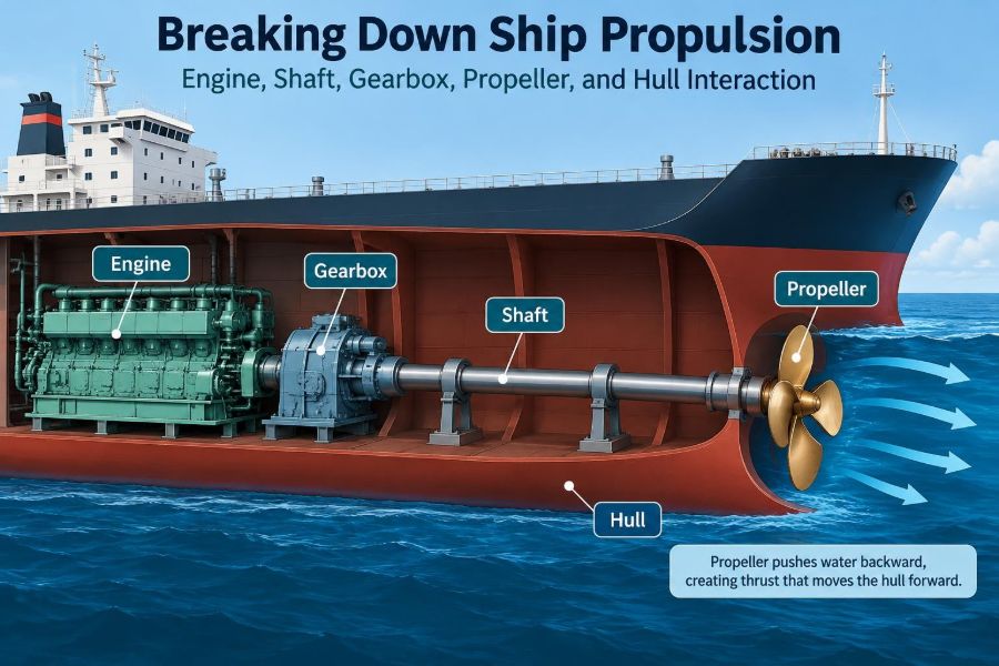

A ship may appear to move because its propeller turns, but that visible rotation is only the final step in a long energy path. Deep in the engine room, fuel energy becomes torque; torque becomes shaft rotation; rotating blades accelerate water; and the hull converts that interaction into forward motion.
When a vessel is slow to respond, vibrates at a particular speed, consumes more fuel than expected, or struggles to reach contractual speed, the answer is rarely found in one component alone. The engine, gearbox, shaft line, propeller, rudder, and hull are a connected propulsion system.
That connection matters to cadets learning machinery, engineers diagnosing performance, and deck officers interpreting a vessel’s handling. A change made at one end of the system can create consequences somewhere else.
Understanding the chain from engine to water makes many onboard observations easier to explain. It also encourages a more useful question than “Is the propeller working?”: is every part of the propulsion system working together at the intended operating point?
⚙️ Propulsion Is an Energy-Conversion Chain
Marine propulsion converts stored energy into thrust. In a conventional mechanical arrangement, the sequence is engine power, rotational torque, shaft power, propeller thrust, and finally ship motion through water.
Every conversion has losses. Friction in bearings, gear tooth contact, seal drag, turbulence around the hull, and swirl in the propeller wake all consume part of the available energy. Good design reduces these losses without sacrificing reliability, safety, or manoeuvrability.
🧭 The Difference Between Power, Torque, and Thrust
Power is the rate at which work is done, usually expressed in kilowatts or megawatts. Torque is the turning effort delivered by the engine or motor to the shaft. Thrust is the forward force developed by the propeller.
A useful analogy is a bicycle: pedal force resembles torque, pedalling rate resembles rotational speed, and the force at the tyre-road contact drives the bicycle forward. On a ship, torque and shaft speed must produce useful thrust in water rather than merely churn it.
🔥 What the Main Engine Actually Supplies
A large two-stroke slow-speed diesel engine can drive a propeller directly because its normal operating speed is already relatively low. Medium-speed diesel engines commonly rotate too quickly for an efficient large propeller and are therefore often connected through reduction gears.
The engine does not deliver identical power under every condition. Its allowable load depends on speed, turbocharger performance, fuel condition, cooling, exhaust temperature, and the manufacturer’s operating limits. A propulsion plant should be managed within its approved load envelope, not simply pushed until a target rpm appears.
📈 Understanding the Engine Load Curve
Propeller-driven ships usually face a steeply rising power demand as speed increases. In simplified terms, propeller absorbed power often changes roughly with the cube of shaft speed under comparable conditions. The real relationship varies with hull condition, weather, draft, and propeller characteristics.
This explains why a modest increase in rpm may require a disproportionately larger increase in engine power and fuel. It also explains why fouling, heavy weather, or a damaged propeller can move the engine toward overload at a speed that previously seemed routine.
🔩 Direct Drive Versus Geared Drive
Direct drive couples the main engine to the propeller shaft with no reduction gearbox. It is mechanically straightforward, has fewer major power-transmission components, and is well suited to low-rpm engines turning large propellers.
A geared arrangement allows a faster engine to operate at a more favorable speed while the propeller turns slower. The added flexibility comes with a gearbox, lubrication system, clutching arrangements in some designs, and additional alignment and maintenance requirements.
| Arrangement | Typical advantage | Key consideration |
|---|---|---|
| Direct-drive slow-speed diesel | Simple main power path and large slow propeller | Less freedom to select engine and propeller speeds independently |
| Geared medium-speed diesel | Compact engine installation and flexible machinery layouts | Gear condition, oil cleanliness, and gear losses require close attention |
| Diesel-electric propulsion | Flexible placement and electrical power sharing | Multiple energy conversions and more electrical equipment |
⚙️ What a Reduction Gearbox Changes
A reduction gearbox lowers engine rpm while increasing torque at the output shaft, approximately in proportion to the reduction ratio after allowing for losses. It does not create power; it trades rotational speed for turning effort.
For example, a medium-speed engine may run efficiently at several hundred rpm while a large propeller works better at a much lower speed. The gearbox lets both components approach their intended range. Gear tooth loading, backlash, bearing condition, and lubricant quality are therefore propulsion concerns, not isolated gearbox issues.
🛢️ Gear Oil Is a Working Component
Gear oil forms a protective film between loaded gear teeth and supports bearings, while also carrying heat away from contact zones. Its viscosity, cleanliness, additive condition, and water content affect the ability of that film to survive.
Cloudy oil, rising particle levels, abnormal temperatures, or unusual magnetic plug debris warrant investigation according to the vessel’s maintenance procedures. Sampling trends are often more informative than one isolated result because wear develops over time.
🔗 The Shaft Line Carries More Than Rotation
The shaft line transmits torque from engine or gearbox to the propeller, but it also transmits axial force. Propeller thrust must ultimately be passed into the ship’s structure through a thrust bearing or thrust block.
Its components may include intermediate shafts, couplings, bearings, seals, stern tube equipment, and a tail shaft. A fault in any of these can limit propulsion even when the engine itself appears healthy.
📐 Alignment Is Not Just a Shipyard Measurement
Shaft alignment means positioning the engine, gearbox, bearings, and shaft sections so that loads remain within acceptable limits during operation. It is not simply a matter of making two flange faces look level while cold and stationary.
The hull flexes with loading and sea conditions, machinery warms up, and bearing positions can change slightly. Designers account for these effects, but worn chocks, foundation movement, bearing wear, or hull distortion can alter the intended alignment.
🧱 Why Bearing Loads Need Attention
Shaft bearings support a heavy rotating line while allowing an oil film to separate metal surfaces. Incorrect load distribution can lead to elevated bearing temperature, wiped white metal, vibration, or accelerated shaft damage.
Changing one bearing height affects neighboring bearings, so adjustment is a controlled specialist task. A quick correction based only on one temperature reading may transfer the problem elsewhere rather than solve it.
🌊 The Stern Tube Keeps Sea and Machinery Apart
The stern tube supports the tail shaft where it passes through the hull. Its arrangement may use oil-lubricated bearings and seals or a water-lubricated system, depending on vessel design and environmental requirements.
Seal performance deserves attention because leakage can mean seawater entering a lubricated system, lubricant entering the sea, or both. Leakage rates and acceptable conditions depend on the installed equipment and applicable operating procedures; assumptions should never replace the maker’s guidance.
🌀 The Propeller Turns Torque Into Thrust
A propeller blade is shaped like a rotating hydrofoil. As it moves through water, it creates a pressure difference and changes the water’s momentum aft. The equal and opposite reaction provides forward thrust to the vessel.
A propeller cannot produce thrust without leaving energy in the water. Ideally, it accelerates a large mass of water by a modest amount rather than a small mass by an extreme amount, which is one reason large, slow-turning propellers are often efficient for displacement ships.
📏 Diameter, Pitch, and Blade Area
Diameter is the circle traced by the blade tips. Pitch is the theoretical forward distance a propeller would advance in one revolution through a solid material, much like a screw. Blade area influences how much loading the propeller can carry.
A larger diameter can improve efficiency when draft, hull clearance, and structural limits permit it. Higher pitch can demand more torque at a given rpm. These variables are selected as a set; increasing one without considering the others can produce an unsuitable match.
↪️ Fixed-Pitch and Controllable-Pitch Propellers
A fixed-pitch propeller has blades set permanently at one angle. Shaft direction and speed are used to control thrust, although reversing depends on the propulsion arrangement.
A controllable-pitch propeller changes blade angle in service. It can provide rapid thrust changes while keeping shaft rotation in one direction, which can be valuable for manoeuvring and certain operating profiles. Its hub mechanism, hydraulic system, and pitch feedback add complexity and require disciplined maintenance.
💨 Cavitation Is a Pressure Problem
Cavitation occurs when local pressure on a blade falls sufficiently for vapor-filled cavities to form and then collapse as pressure recovers. The collapse can produce noise, vibration, surface erosion, and loss of effective thrust.
It is not solved simply by choosing a “stronger” propeller. Designers manage blade loading, area, pitch distribution, immersion, tip clearance, and wake conditions. Operators can also avoid unnecessary rapid loading changes where the vessel’s procedures and operating situation allow.
🔊 Propeller Noise and Vibration Have Many Paths
Propeller forces vary as each blade passes through the uneven water flow behind the hull. These periodic forces can excite shaft vibration, hull vibration, rudder vibration, or noise transmitted through structure and water.
A vibration complaint should therefore be described carefully: the rpm range, draft, sea state, loading condition, whether it changes with pitch, and where it is felt. “The ship vibrates” is an observation; a useful diagnosis needs a pattern.
🏠 The Hull Creates the Propeller’s Inflow
The propeller does not work in undisturbed open water. The hull slows and redirects water flowing toward it, creating a non-uniform wake. The stern shape, appendages, bilge keels, shaft brackets, and draft condition all influence what reaches the propeller.
This is why a propeller selected from open-water data alone is not enough. Naval architects design the hull and propeller together, seeking a practical compromise among efficiency, cavitation behavior, vibration, structural clearance, and manoeuvring.
🚤 Wake Fraction and Thrust Deduction
Two hull-propeller interaction terms help explain why ship propulsion is more complex than an isolated propeller test. Wake fraction describes, in simplified form, how the water approaching the propeller is slower than the ship’s speed. Thrust deduction reflects how propeller action changes pressure around the hull and increases the thrust needed to tow it.
These are design-analysis concepts rather than routine watchkeeping calculations. Their practical message is clear: the hull affects propeller performance, and the propeller affects hull resistance.
🧼 Hull and Propeller Fouling Raise Demand
Marine growth, slime, rough coatings, and damaged paint increase skin friction over the hull. Fouling on propeller blades changes their surface condition and can disturb the carefully designed flow around them.
The result may be higher fuel use, lower attainable speed, increased torque demand, or vibration. A clean hull and propeller do not make a ship lossless, but they help the machinery deliver its available power to useful motion rather than extra resistance.
⚓ Draft and Trim Change the Operating Point
A vessel’s displacement, draft, and trim alter resistance and the flow into the propeller. A lightly loaded ship may have different stern immersion and propeller submergence from a deeply laden one, while excessive trim can add resistance or worsen inflow.
For a hypothetical ship on two similar routes, a change in cargo condition may explain different rpm, fuel consumption, and vibration behavior even when the engine and weather appear unchanged. Performance comparisons should therefore record loading condition, not just speed and power.
🌦️ Weather Can Look Like a Machinery Fault
Head seas, wind, current, shallow water, and increased rudder activity can change the power required to maintain a given speed. In heavy conditions, the propeller may periodically emerge or encounter disturbed flow, producing load fluctuations.
Before concluding that an engine has lost power, compare conditions fairly. Engine parameters, shaft rpm, fuel index or command, exhaust temperatures, vessel draft, sea state, and speed through water all help separate a machinery issue from an external resistance increase.
🧮 Matching Engine and Propeller Matters
The engine’s available torque-speed characteristic must be compatible with the propeller’s absorbed-power curve. If the propeller absorbs too much power at a given rpm, the engine can overload; if it absorbs too little, the engine may operate inefficiently or fail to reach its intended condition.
Matching changes over a ship’s life. Fouling, propeller modification, engine derating, fuel changes, altered trading patterns, and hull damage can shift the real operating point away from the original design assumption.
📊 Reading a Sea Trial or Performance Trend
Speed-power data are useful only when their context is understood. Calm-water trials, corrected trials, daily noon reports, and rough-sea operating data answer different questions and should not be treated as interchangeable.
A sensible trend review looks for persistent changes under broadly comparable conditions. A gradual rise in required shaft power can suggest resistance growth; a sudden step change may point toward damage, a control issue, sensor error, or an operational change that deserves inspection.
🧰 Common Symptoms and Sensible First Checks
Symptoms often overlap, so diagnosis should start with evidence rather than a favorite explanation. Check alarms, trend data, recent maintenance, weather, draft, and operational changes before dismantling equipment.
- High exhaust temperatures with normal demand: consider engine-side combustion, air, cooling, or fuel issues.
- High torque or load at reduced speed: consider hull resistance, propeller condition, weather, or a mismatch.
- New vibration at a narrow rpm band: consider resonance, propeller damage, bearing condition, or shaft-line alignment.
- Stern tube abnormalities: follow maker limits and investigate seal, lubrication, temperature, and water-ingress indicators.
🛑 Avoid the “More Power” Response
Increasing power can be necessary for safety, schedule recovery, or weather avoidance, but it is not a diagnostic repair. If added power produces little speed gain, the vessel may be operating against sharply rising resistance or suffering poor propulsive efficiency.
Continuing to load machinery through abnormal vibration, high bearing temperatures, or overload indications can turn a manageable defect into major damage. The correct response depends on the specific vessel, risk to navigation, and approved procedures.
🛠️ Maintenance Protects System Efficiency
Propulsion reliability comes from routine attention to the complete chain: combustion condition, lubrication, cooling, gear inspections, oil analysis, coupling checks, bearing monitoring, stern tube records, and underwater hull and propeller condition.
Planned maintenance should be combined with operational trend monitoring. A component may pass an individual inspection while the overall system still signals declining efficiency through increasing fuel demand or worsening vibration.
🧑🏭 Communication Across Shipboard Departments
Deck and engine teams observe different parts of the same problem. Deck personnel may notice poor turning response, steering vibration, speed loss, or changing weather; engine personnel see temperatures, pressures, torque, rpm, and machinery alarms.
Useful reports connect those observations. Rather than reporting only “speed low,” record the ordered speed, actual rpm, pitch where fitted, draft, trim, sea state, current estimate, machinery readings, and time the change began.
🔌 Electric and Hybrid Systems Still Follow the Same Physics
Electric motors can replace or supplement mechanical engines, while batteries, shaft generators, and power electronics change how energy reaches the propeller. Azimuthing thrusters may combine motor, steering, and propulsor in one unit.
These systems offer different layout and operating possibilities, but they do not remove the central challenge. Motor torque, propulsor characteristics, hull resistance, cavitation limits, and water flow must still be matched.
🧠 A Practical Troubleshooting Sequence
A structured sequence prevents technicians from jumping directly to the most visible component. Start by confirming the operating condition and measurement quality, then compare current behavior with reliable baseline data.
- Establish draft, trim, weather, speed through water, and propulsion command.
- Check engine or motor limits, torque, rpm, temperatures, pressures, and alarms.
- Review recent changes in fuel, maintenance, hull condition, or machinery configuration.
- Identify whether the symptom follows rpm, pitch, vessel speed, or sea condition.
- Escalate inspection and specialist assessment according to the vessel’s procedures.
🧩 Designing for the Whole Mission
A cargo ship optimized for steady ocean passage, a tug requiring high bollard pull, a ferry needing frequent acceleration, and an offshore vessel holding position do not need the same propulsion solution. Propeller type, engine arrangement, reduction ratio, redundancy, and hull form follow the vessel’s mission.
There is no universally best propulsor. A choice that improves low-speed pulling force may compromise cruise efficiency, while a highly efficient single-screw arrangement may offer less redundancy than a multi-unit plant.
✅ The Core Principle: Treat Propulsion as One System
The engine creates power, the gearbox selects a useful speed-torque relationship, the shaft line transmits torque and thrust safely, the propeller accelerates water, and the hull shapes both resistance and inflow. None can be properly understood in isolation.
For students, this systems view turns separate textbook topics into one physical process. For working professionals, it supports better monitoring, clearer fault reports, and decisions that protect both fuel efficiency and machinery life.
A ship moves efficiently only when its engine, transmission, shaft line, propeller, and hull are matched to one another and to the conditions in which the vessel operates. That is the thread connecting everyday watchkeeping readings to the deepest principles of naval architecture and marine engineering. 🚢⚙️🌊