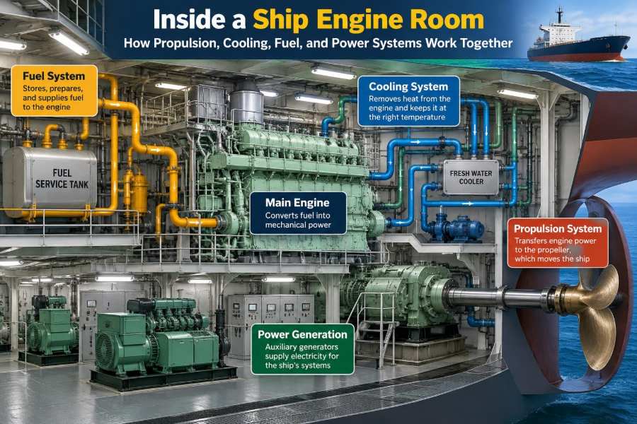

A ship can appear calm from the deck: containers stacked in rows, passengers moving through public spaces, or a bridge team watching the horizon. Several decks below, however, the engine room is managing heat, pressure, motion, electrical demand, and fuel flow every second.
When a vessel accelerates, a pump starts, a refrigerator holds its temperature, or a steering command reaches the rudder, several engineering systems must respond together. A failure in one may quickly place extra strain on the others.
That interdependence is what makes marine engineering more than a study of individual machines. The engine room is a working system of systems, designed with redundancy, alarms, procedures, and people who must understand cause and effect.
Seeing how the main engine, propeller, cooling circuits, fuel treatment plant, generators, and control systems connect provides a practical foundation for anyone entering shipboard engineering.
⚙️ The Engine Room as an Integrated Plant
An engine room is not simply the compartment containing the main engine. It is the machinery space where a vessel produces propulsion, generates electricity, manages fluids, rejects heat, and supports essential services.
The machinery layout varies by ship type, size, propulsion arrangement, and class requirements. Yet the operating principle is consistent: energy enters as fuel or stored electrical energy, is converted into useful power, and leaves partly as motion and partly as waste heat.
Engineers monitor that energy path continuously. Temperatures, pressures, tank levels, vibration, exhaust condition, and electrical load tell the team whether the plant is balanced.
🧭 Why System Interaction Matters at Sea
A ship cannot simply pull over when machinery behaves unexpectedly. It must retain enough propulsion, steering, electrical power, cooling, and pumping capacity to remain safe in changing weather and traffic conditions.
Consider a high jacket-water temperature on a main engine. The immediate problem might be restricted cooling-water flow, but the underlying cause could be a fouled sea inlet, a weak pump, an incorrectly positioned valve, or low expansion-tank level.
Good troubleshooting therefore starts by asking what changed in the system, not merely which alarm appeared first.
🔥 From Fuel Energy to Shaft Power
Most large commercial ships use diesel engines that burn fuel inside cylinders. The expanding combustion gases push pistons downward, turning a crankshaft through connecting rods.
That rotating output is mechanical power. Depending on the arrangement, it may drive a propeller directly, pass through a reduction gearbox, or turn an electrical generator for electric propulsion.
Only part of the fuel’s chemical energy becomes useful shaft power. Much of the remainder appears as heat in exhaust gas, cooling water, lubricating oil, and surrounding machinery. Removing that heat safely is one of the engine room’s central tasks.
🏗️ The Main Engine and Its Core Cycle
Large slow-speed two-stroke diesel engines are common on oceangoing cargo ships because they can turn a large propeller efficiently at relatively low speed. Many other vessels use medium-speed four-stroke engines, often with gearboxes.
In either case, the engine needs accurately timed air supply, fuel injection, lubrication, cooling, and exhaust removal. Modern engines use electronic control on many installations, but the physical requirements remain unchanged.
A combustion engine is unforgiving of poor fundamentals. Inadequate air, contaminated fuel, weak lubrication, or overheating can quickly affect reliability and component life.
🌀 How the Propeller Creates Thrust
A propeller converts shaft rotation into thrust by accelerating water aft. Its blades are shaped like rotating hydrofoils, producing a pressure difference that moves the ship forward.
The propeller works in a demanding environment. Hull fouling, rough seas, shallow water, and damage to blade surfaces can all alter the load seen by the engine.
For a fixed-pitch propeller, speed is commonly controlled by changing engine revolutions. A controllable-pitch propeller can vary blade angle while shaft speed remains more nearly constant, which can be useful for maneuvering and certain operational profiles.
🔩 Shaft Lines, Bearings, and Seals
Between the engine and the propeller lies the shaft line: couplings, shafts, bearings, and usually a stern tube where the shaft passes through the hull. These components must transmit high torque while staying aligned.
Bearings support the shaft and maintain a lubricating film that prevents metal-to-metal contact. Misalignment, inadequate lubrication, or abnormal vibration can raise bearing temperature and cause serious damage if not addressed.
The stern-tube sealing arrangement limits seawater ingress and lubricant loss. Its condition is monitored because a seal problem affects both machinery reliability and environmental protection.
🧰 Direct Drive, Gearboxes, and Electric Propulsion
Propulsion architecture determines how power flows through the vessel. A direct-drive slow-speed engine connects closely to the propeller shaft, avoiding a reduction gearbox and providing a straightforward mechanical path.
Medium-speed engines rotate faster than a large propeller normally should, so a gearbox reduces speed and increases torque at the shaft. In diesel-electric plants, engines drive generators and electric motors turn the propeller.
| Arrangement | Main strength | Typical operational consideration |
|---|---|---|
| Direct diesel drive | Simple power path and efficient cruising operation | Less flexible engine placement |
| Geared diesel drive | Allows higher-speed engines with suitable propeller speed | Gearbox condition becomes critical |
| Diesel-electric propulsion | Flexible machinery layout and power sharing | Requires sophisticated electrical management |
No arrangement is universally best. Vessel mission, space, redundancy needs, maneuvering demands, and fuel profile all influence the choice.
🌬️ Air Supply and Turbocharging
An engine must receive enough clean air to burn its injected fuel effectively. Air filters, turbochargers, charge-air coolers, and scavenge spaces or intake manifolds form part of that path.
A turbocharger uses energy in the exhaust gas to spin a turbine connected to an air compressor. The compressor packs more air into the engine, allowing more complete combustion and higher power from a given engine size.
Charge air is cooled after compression because cooler air is denser. A dirty charge-air cooler or restricted air filter can reduce available air and contribute to poor combustion.
💨 Exhaust Gas and Heat Recovery
Exhaust gas carries significant heat away from the engine. The exhaust system guides it through manifolds, turbochargers, silencers, and sometimes heat-recovery equipment before discharge.
Some ships use exhaust gas economizers to produce steam or heat water. This can reduce the need to fire an auxiliary boiler while the main engine is operating at a suitable load.
Heat recovery is useful, but it introduces maintenance needs. Soot deposits, corrosion risk, and gas-side fouling must be managed so the equipment does not restrict exhaust flow or create an overheating hazard.
❄️ Why Engines Need Several Cooling Circuits
Cooling is rarely a single loop. Separate circuits allow engineers to maintain different components at temperatures appropriate to their duties while controlling corrosion and contamination.
Fresh water commonly circulates inside the engine through jackets around cylinder liners and heads. Other fresh-water loops may serve lubricating-oil coolers, charge-air coolers, generators, or auxiliary machinery.
Seawater usually acts as the final heat sink through a cooler rather than flowing directly through sensitive engine passages. This separation helps reduce saltwater corrosion and deposits inside the engine.
🌡️ The Jacket-Water Circuit
Jacket water absorbs heat from cylinder liners, cylinder heads, and other hot engine components. It is treated freshwater, not ordinary tap water, because its chemistry must be controlled to limit corrosion and scale formation.
A typical circuit includes a circulation pump, temperature-control valve, cooler, expansion tank, vents, and alarms. The expansion tank provides a static head, accommodates thermal expansion, and helps reveal losses.
Running too cold can reduce efficiency and increase deposits; running too hot weakens lubricating conditions and raises thermal stress. The correct target is set by the engine maker and operating instructions.
🌊 Central Cooling and the Seawater Side
In a central cooling system, seawater cools a central fresh-water circuit through plate or shell-and-tube heat exchangers. That fresh water then cools multiple consumers within the machinery plant.
This arrangement reduces the number of components exposed directly to seawater. It also makes treatment and leak detection more manageable on the closed fresh-water side.
Sea chests, strainers, pumps, valves, and coolers still need close attention. Marine growth, debris, silt, or ice conditions can restrict seawater supply and reduce the plant’s ability to reject heat.
🧪 Water Treatment Protects the Plant
Cooling water is a working fluid, not just water. Dissolved salts, oxygen, and unsuitable chemical balance can promote corrosion, scaling, or microbiological growth depending on the circuit.
Engine-room staff test cooling water according to the vessel’s treatment program and manufacturer guidance. Chemicals are added carefully, because over-treatment can be as harmful as under-treatment.
A persistent need for make-up water deserves investigation. It may indicate a small external leak, a leaking cooler, or—in more serious cases—an internal engine leak.
🛢️ Fuel Storage Begins in the Double Bottom
Fuel often arrives aboard into storage tanks, which may be arranged low in the ship for stability and protection. From there, it is transferred to settling tanks and then to service tanks near the point of use.
This staged arrangement provides time for water and heavier contaminants to settle before fuel reaches fine treatment equipment. Tank heating may be needed for viscous residual fuels so they remain pumpable.
Tank sounding, level alarms, overflow prevention, and correct valve line-up matter as much as the fuel itself. A transfer error can contaminate the wrong tank, overflow into a space, or leave a service tank unexpectedly low.
🌀 Fuel Treatment Before the Engine
Marine fuel may contain water and particulate contamination. Centrifugal separators use rapid rotation to separate liquids and solids by density before fuel enters the day-to-day service system.
After separation, booster pumps, heaters, viscosity control equipment, and filters prepare fuel for injection. The details differ between distillate and residual fuels, as well as between engine designs.
Filters are a final defense, not a substitute for good treatment. A sudden rise in filter differential pressure can indicate contamination upstream or a change in fuel condition.
🎯 Injection and Combustion Quality
The fuel-injection system meters and delivers fuel at precisely controlled timing and pressure. Fine atomization helps fuel mix with air and burn efficiently within the available time.
Injector faults, poor fuel viscosity, low fuel temperature, or inadequate air supply can lead to uneven combustion. Signs may include abnormal exhaust temperatures, smoke, rough running, or changes in engine load balance.
These symptoms are clues rather than diagnoses by themselves. Engineers compare them with trend data, cylinder pressures where available, and the condition of associated systems before taking action.
🛡️ Fuel Safety and Leak Prevention
Fuel under pressure near hot engine surfaces presents a fire risk. Engine rooms therefore use shielded high-pressure fuel pipes, leak-off arrangements, insulation on hot surfaces, and rapid shut-off provisions.
Good housekeeping is a safety control. A small seepage that is ignored can wet lagging, collect in bilges, or become dangerous when it contacts a hot surface.
- Investigate unusual fuel consumption rather than assuming it is operational variation.
- Keep drip trays, save-alls, and bilges clean enough for leaks to be seen quickly.
- Never defeat an alarm or protective device simply to keep equipment running.
⚡ Generators Supply the Ship’s Electrical Life
Auxiliary diesel generators convert fuel energy into electricity for pumps, lighting, navigation equipment, accommodation services, cargo systems, and many other consumers. On some vessels, shaft generators or battery systems contribute as well.
Electrical demand changes sharply between sea passage, maneuvering, cargo work, and port stay. A generator plant must have enough capacity not only for normal demand but also for essential services and starting large motors.
The generator engine, alternator, cooling system, fuel system, and switchboard are all part of the same electrical supply chain.
🔌 Synchronizing Generators and Sharing Load
Before an incoming generator is connected to a live busbar, its voltage, frequency, and phase relationship must be matched to the system. This is synchronization.
Once connected, generators share active power, measured in kilowatts, and reactive power, often expressed in kilovolt-amperes reactive. Governors primarily influence active-load sharing; excitation systems influence reactive-load sharing.
Incorrect sharing can overload one generator while another carries too little load. Automation helps, but watchkeepers still need to understand what the instruments show and why.
🚨 Blackout Prevention and Recovery
A blackout is the loss of the main electrical supply. It can stop pumps, ventilation, lighting, automation, and propulsion-related auxiliaries, although emergency arrangements are designed to support critical functions.
Preventing blackout involves maintaining generators, avoiding careless switching, monitoring loading, and ensuring standby machinery is ready. A poorly prepared standby set is not genuine redundancy.
If blackout occurs, recovery follows vessel-specific procedures: establish emergency power, identify the cause, restore generation safely, then reconnect loads in a controlled order. Restarting every consumer at once can overload the recovering plant.
🔋 Emergency Power Has a Separate Purpose
An emergency generator or other approved emergency source supplies selected essential loads when the main source fails. Depending on vessel design, these may include emergency lighting, communications, navigation aids, alarms, and equipment needed for safety.
Emergency power is deliberately separated from the normal supply as far as practicable. Its reliability depends on testing, fuel availability, starting arrangements, battery condition, and the integrity of its distribution path.
It is not intended to preserve every comfort or commercial service. Its purpose is to preserve a safe minimum capability while the main plant is recovered.
🛞 Steering Gear Depends on Hydraulic and Electric Power
The steering gear converts commands from the bridge into rudder movement. Many systems use electric motors driving hydraulic pumps, which pressurize oil to move rams or rotary actuators.
Because steering is safety-critical, ships commonly have redundant pumps, power supplies, and local control arrangements. A fault in a hydraulic circuit may therefore require a change in operating mode rather than an immediate loss of steering.
Engineers must treat steering tests seriously. A standby pump that has not been tested under realistic conditions may not be available when it is needed most.
💧 Bilge, Ballast, and General Service Systems
Bilge systems collect and remove water that enters machinery spaces through leakage, drainage, or maintenance activities. Bilge water must be handled in accordance with the vessel’s approved equipment and procedures; it is not simply pumped overboard.
Ballast systems move seawater into and out of dedicated tanks to manage draft, trim, stability, and hull stresses. General-service pumps may supply wash water, firefighting lines, or other routine needs.
These systems share pumps, valves, strainers, and pipe runs, so valve discipline is essential. A wrong valve position can cause cross-contamination, loss of suction, or unintended transfer between tanks.
🛢️ Lubricating Oil Does More Than Reduce Friction
Lubricating oil forms a protective film between moving surfaces such as bearings, pistons, gears, and cam mechanisms. It also carries away heat, helps seal certain clearances, and transports contaminants toward filters and purifiers.
Oil condition is monitored through pressure, temperature, filter differential pressure, and laboratory analysis where carried out. Water contamination, fuel dilution, soot, or metallic wear particles can reveal developing faults.
Low oil pressure is especially serious because a bearing can be damaged rapidly when the oil film breaks down. Protective trips are designed to prevent a manageable defect from becoming a major casualty.
📈 Sensors, Alarms, and Human Judgment
Automation systems collect data from transmitters, switches, and sensors throughout the machinery plant. They may alarm, slow down an engine, start standby equipment, or shut down machinery when a limit is exceeded.
An alarm is not a diagnosis. It tells the watchkeeper that a condition requires attention, while the underlying cause may be mechanical, electrical, hydraulic, operational, or instrument-related.
Trend awareness is often more valuable than a single reading. A bearing temperature rising gradually over days can be more informative than a brief normal value recorded during rounds.
👂 Engine-Room Rounds Still Matter
Even highly automated vessels require regular physical rounds. Sight, sound, smell, and touch—used safely—can reveal issues that a control screen may not explain.
An engineer may notice an unusual pump vibration, a warm bearing housing, a fine spray near a flange, or a change in exhaust sound. These observations create context for the numerical data.
Useful rounds are systematic. They compare actual conditions with normal conditions, record abnormalities clearly, and ensure that defects are handed over between watches.
🧯 Fire Safety Is Designed Into the Machinery Space
Engine rooms contain fuel, hot surfaces, electrical equipment, and rotating machinery. Fire protection combines prevention, detection, containment, and fixed firefighting capability.
Insulation, shielding, ventilation controls, fire doors, detection systems, quick-closing valves, remote stops, and fixed extinguishing systems each serve different functions. They are effective only when maintained and used within established procedures.
In a machinery-space fire, unnecessary actions can worsen conditions. Crew members must follow the vessel’s emergency plan, accounting procedures, and command structure rather than improvising under pressure.
🦺 Safe Maintenance Starts with Isolation
Before maintenance, engineers identify every energy source: electrical supply, pressure, hydraulic movement, rotating parts, stored heat, fluid head, and automatic starting signals. Equipment must be isolated, secured, and verified safe before work begins.
This is particularly important for pumps and motors that can start automatically, tanks that can drain unexpectedly, and systems with pressure trapped behind closed valves.
A permit-to-work system does not replace technical judgment. It provides a structured way to plan the task, communicate hazards, confirm isolations, and return equipment safely to service.
🔧 Planned Maintenance and Condition Monitoring
Planned maintenance uses schedules and manufacturer guidance to organize tasks such as inspections, oil changes, filter renewal, testing, and overhaul. It helps prevent maintenance from being postponed until failure occurs.
Condition monitoring adds evidence from vibration, oil analysis, temperature trends, performance data, and inspections. It can help engineers decide whether a component needs attention earlier or can safely remain in service.
The balanced approach is neither blind adherence to a calendar nor waiting for a breakdown. Maintenance decisions should consider equipment condition, operational risk, spare availability, and approved procedures.
⚠️ Common Mistakes When Reading Engine-Room Problems
A common error is treating a symptom as the cause. Replacing a tripping pump motor, for example, may not solve the issue if the pump is mechanically seized or the discharge valve is shut.
Another mistake is changing several settings at once. That can hide the original fault and make it difficult to know which intervention changed the result.
- Confirm instrument validity before making major decisions from one reading.
- Check simple causes first: valve position, tank level, power supply, filter condition, and control mode.
- Use drawings, manuals, and past records instead of relying solely on memory.
- Record temporary repairs so they are not mistaken for permanent solutions.
🧩 A Practical Fault-Finding Sequence
Effective troubleshooting is structured. First, make the situation safe and protect essential functions. Then define the symptom precisely: what is abnormal, when did it begin, and what equipment or operation changed beforehand?
Next, trace the system using a diagram and verify each stage with observations. For a cooling problem, that could mean checking tank level, pump operation, suction condition, valve alignment, differential pressures, and cooler performance.
Finally, confirm the repair by monitoring the system after restart. A normal alarm state alone is not enough; temperatures, pressures, leakage, and load behavior should return to an acceptable pattern.
🌱 Efficiency and Emissions Are System Questions
Fuel efficiency is influenced by hull condition, propeller condition, engine load, combustion quality, auxiliary demand, route, weather, and operational decisions. The engine room supports efficiency, but it cannot deliver it alone.
Likewise, emissions control may involve fuel selection, engine tuning, exhaust treatment, energy management, and compliance with applicable vessel and trading requirements. The exact solution depends on the ship and its operating area.
Engineers contribute by keeping machinery clean, correctly adjusted, and properly monitored. Small losses in cooling performance, air supply, or fuel treatment can accumulate into avoidable fuel use and emissions.
🤝 Communication Connects the Technical Systems
Bridge and engine teams depend on clear communication during maneuvering, restricted waters, maintenance, and emergencies. The bridge needs realistic information about propulsion availability, generator status, and limitations.
The engine room needs notice of speed changes, arrival plans, cargo operations, and unusual operating demands. That allows machinery to be lined up, warmed through, tested, or placed on standby in time.
Accurate handovers are equally important. A brief but specific note about a fluctuating pressure or a standby pump under observation can prevent the next watch from inheriting an unexplained risk.
🧠 The Core Principle: Manage Energy, Heat, and Risk Together
Propulsion produces motion, but it also creates heat that cooling systems must remove. Fuel systems feed engines and generators; electrical systems run the pumps and controls that keep those machines alive. Lubrication protects the moving parts, while monitoring and people connect every process.
The most capable marine engineers do not view these as isolated subjects. They understand dependencies: loss of electrical power can stop cooling; poor cooling can limit propulsion; fuel contamination can affect both main and auxiliary engines.
A reliable ship engine room is achieved by maintaining the relationships between systems, not by focusing only on the largest machine.
When propulsion, cooling, fuel, power, safety, and watchkeeping are understood as one coordinated plant, engineers can make sounder decisions long before a small abnormality becomes a major problem. 🚢⚙️🌊