
A container ship arriving at a port can look almost unreal: a floating rectangle of steel carrying stacked boxes higher than nearby buildings. From shore, it is easy to see the cargo. Much harder is seeing the engineering that lets the vessel bend with waves, survive corrosion, generate its own power, and remain controllable in confined water.
For the crew, a cargo ship is not simply a very large vehicle. It is a self-contained industrial plant, electrical network, accommodation block, pumping system, and structural beam that happens to travel through an unpredictable fluid.
Building one therefore involves far more than joining steel plates together. Thousands of design decisions must work together—from the shape of the bow to the routing of a single fuel pipe.
Following the construction sequence makes marine engineering feel less abstract. It shows why shipyards divide a giant ship into manageable pieces, why testing matters as much as fabrication, and why a vessel is only finished when its systems work together at sea.
🌊 What Makes a Massive Cargo Ship Different
Large cargo ships include container ships, bulk carriers, tankers, vehicle carriers, and general cargo vessels. Their cargoes differ, but each must be designed around a central trade-off: carrying useful payload while retaining enough strength, stability, speed, endurance, and safety margin.
A ship is often described by dimensions such as length overall, beam (width), draft (depth below the waterline), and deadweight. Deadweight is the mass a vessel can safely carry, including cargo, fuel, water, stores, crew, and consumables—not the ship’s own lightweight mass.
As ships grow, loads do not merely become larger versions of small-ship loads. Hull girder bending, local container-stack loads, sloshing in tanks, vibration, and port restrictions all become more demanding engineering problems.
🧭 Starting With the Owner’s Requirements
Construction begins long before steel is cut. An owner and designer define the ship’s intended route, cargo, service speed, loading pattern, fuel strategy, port limits, and expected operating profile.
A bulk carrier serving shallow terminals may be limited by draft. A container vessel may be limited by bridge clearance or crane reach. A tanker requires segregated tanks, extensive pumping arrangements, and systems suited to its particular cargo.
These requirements form a design brief. Changing them late can affect almost every discipline, so early decisions deserve careful scrutiny. A wider hull may improve capacity and stability, for example, but can increase resistance and prevent access to certain berths.
📐 Turning a Concept Into a Design
Naval architects develop the hull form and principal dimensions, while marine, electrical, structural, piping, and production engineers develop the supporting details. Modern projects use a shared three-dimensional model to coordinate equipment, structure, cable routes, and pipe runs.
The early design must demonstrate compliance with applicable flag-state rules, international conventions, and classification-society requirements. Classification societies independently review aspects of design and construction against their technical rules; their involvement does not replace the owner’s responsibility or the shipyard’s quality control.
Design is iterative. If stability calculations indicate insufficient margin, designers may alter tank arrangement, hull form, lightship weight, or loading restrictions. If an engine room becomes too crowded, the machinery layout and supporting structure may need revision.
⚖️ Balancing Capacity, Strength, and Efficiency
No cargo ship is optimized for one goal alone. More cargo volume is attractive commercially, but additional structure increases weight. A finer hull can reduce resistance in some conditions, but may reduce internal space or create different structural challenges.
The design team evaluates a set of linked questions:
- Can the hull withstand global bending between wave crests and troughs?
- Will the vessel remain stable through all approved loading conditions?
- Can machinery deliver the required speed without excessive fuel use?
- Can cargo be loaded, secured, discharged, and monitored safely?
- Can the ship be built efficiently in the selected yard?
This is why an apparently simple change, such as moving a bulkhead, can have consequences for cargo capacity, fire boundaries, piping, ballast flow, and structural continuity.
🧱 Choosing Marine-Grade Steel
Most large cargo ship hulls are made principally from shipbuilding steel plate and stiffened panels. The steel grade and thickness depend on location, temperature considerations, stress level, fatigue exposure, and class requirements.
Steel is selected not just for strength but also for toughness and weldability. Toughness is a material’s ability to resist crack propagation and brittle fracture under demanding conditions. This is particularly relevant in cold environments and highly stressed details.
Shipyards receive plates, sections, pipes, and machinery with documentation and identification. Maintaining material traceability helps ensure that the steel installed in a critical structural area is the steel specified by the design.
🏭 Preparing Steel in the Fabrication Shop
Before assembly, steel passes through preparation lines. Plates may be shot-blasted to remove mill scale and then primed with a temporary protective coating suitable for fabrication.
Computer-controlled cutting machines produce plates with precise outlines, openings, bevels for welding, and identifying marks. The cut parts can include flat panels, curved shell plates, webs, brackets, and internal stiffeners.
Accuracy at this stage matters. A small dimensional error repeated across many panels can create a serious fit-up problem later, especially where blocks must join along long seams.
🧩 Building Panels and Subassemblies
A shipyard rarely starts by laying down one enormous hull plate. Instead, it creates subassemblies: stiffened panels, transverse webs, double-bottom units, bulkhead sections, and decks.
Longitudinal stiffeners—slender structural members running along the ship—support plating and help distribute loads. Larger girders and webs provide deeper support where loads are higher. Together, these elements create a lightweight but strong grillage-like structure.
Automation can weld repetitive panel seams efficiently, while complex intersections and access-limited areas still require skilled welders. The goal is not merely speed; it is repeatable quality and controlled distortion.
🔥 Welding the Hull Without Warping It
Welding permanently joins the ship’s steel structure, but concentrated heat also causes expansion and contraction. If unmanaged, this produces distortion: a panel may buckle, a deck may lose fairness, or a block edge may no longer align accurately.
Shipyards control distortion through welding sequence, restraint, heat-input control, and planned allowances. Workers may weld balanced seams on opposite sides of a structure or use automated processes that maintain consistent parameters.
Welding procedures are qualified for the material and joint type. Welders must also be qualified for the work they perform. A visually neat weld is not necessarily sound, which is why inspection continues throughout construction.
🔍 Inspecting Welds and Critical Joints
Quality control combines visual examination with non-destructive testing, or NDT. NDT methods examine a component without cutting it apart.
| Method | What it can help reveal | Typical use |
|---|---|---|
| Visual inspection | Surface profile, alignment, obvious defects | Routine checks before and after welding |
| Ultrasonic testing | Internal discontinuities using sound waves | Butt welds and thicker structural joints |
| Radiographic testing | Internal weld features shown by radiation imaging | Selected critical welds where suitable |
| Magnetic-particle or dye-penetrant testing | Surface or near-surface cracks | Details, repairs, and accessible weld areas |
The chosen method depends on the joint, access, material, and applicable requirements. Inspection findings may lead to repair, further assessment, or acceptance based on defined criteria—not every indication has the same engineering significance.
🧊 Why Shipyards Build in Blocks
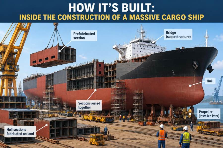
The defining feature of modern shipbuilding is block construction. Rather than assembling an entire vessel piece by piece in a dock, the yard constructs large three-dimensional modules in workshops or covered assembly areas.
A block might contain part of the double bottom, a cargo hold, engine-room structure, or accommodation spaces. It can include foundations, piping, cable trays, insulation supports, and even installed equipment before it reaches the building dock.
Block construction moves work into safer, more controlled positions. It also allows several areas of the ship to be fabricated simultaneously, reducing the time the hull occupies an expensive dock or slipway.
🏗️ The Role of Pre-Outfitting
Pre-outfitting means installing systems and equipment before a block is joined into the full ship. It can include pipes, valves, ventilation ducts, electrical trays, machinery foundations, ladders, doors, and insulation pins.
Installing a pipe when both sides of a block are open is generally easier than installing it through a small manhole after completion. But pre-outfitting demands excellent coordination: a misplaced pipe spool can prevent a structural block from mating correctly.
Production engineers use the 3D model to identify clashes before fabrication. In practice, site conditions can still differ from a model, so controlled measurements and timely feedback remain essential.
🧱 Creating the Double Bottom
Many cargo ships have a double bottom: an inner bottom forming the floor of cargo spaces and tanks, plus an outer shell forming the ship’s underside. The space between them contains structure and may include ballast, fuel, or other tanks, depending on the vessel arrangement.
The double bottom contributes to longitudinal strength and offers a degree of separation between internal spaces and the sea. It is not a guarantee against damage, but it can reduce the likelihood that a minor grounding immediately reaches certain tanks or holds.
Its internal structure must still allow inspection, drainage, and maintenance. A theoretically strong arrangement can become difficult to operate if access and water-trapping details are neglected.
🚧 Forming Bulkheads and Watertight Divisions
Transverse bulkheads divide the vessel into compartments. Some are designed as watertight boundaries, limiting the spread of flooding if a hull compartment is breached.
Watertight integrity depends on more than steel plating. Pipe penetrations, cable transits, doors, hatches, ventilation closures, and weld details must all preserve the intended boundary. One incorrectly installed penetration can undermine a carefully designed subdivision.
Bulkheads also carry structural loads and may separate cargo holds, machinery spaces, tanks, and accommodation. Their arrangement is therefore shaped by both safety rules and operational needs.
⚓ Assembling the Hull in the Dock
Once major blocks are ready, heavy-lift cranes transfer them to the building dock or slipway. Survey teams establish reference points and check alignment as each block is positioned.
Block joints are fitted, welded, inspected, and released in a planned sequence. Hull erection is a controlled geometric exercise: the ship must emerge with the correct length, beam, fairness, and alignment of critical features such as shaft lines and rudder bearings.
Large blocks can weigh hundreds of tonnes or more, depending on the yard and vessel. Lifting plans account for the block’s center of gravity, temporary lifting lugs, crane capacity, wind, rigging angles, and exclusion zones.
📏 Controlling Alignment and Dimensional Accuracy
A ship hull can tolerate neither casual measurements nor perfect mathematical assumptions. Steel changes shape slightly through cutting, welding, lifting, and temperature variation. Production teams use surveys, reference datums, and planned shrinkage allowances to manage these effects.
Alignment is especially significant in propulsion machinery. The main engine, gearbox where fitted, shaft bearings, stern tube, and propeller must form a controlled line. Excessive misalignment can overload bearings, increase vibration, and damage seals.
Final alignment is checked under specified conditions because hull deflection changes as the vessel is supported, launched, ballasted, and loaded.
🛠️ Installing the Main Propulsion Plant
Many large ocean-going cargo ships use a slow-speed two-stroke diesel engine connected directly to a fixed-pitch propeller. Other arrangements use medium-speed engines with gearboxes, diesel-electric systems, or alternative fuel-compatible machinery.
The main engine is mounted on substantial foundations designed to distribute its weight and dynamic loads into the hull. It requires fuel supply, lubrication, cooling, starting air, exhaust, control systems, drainage, and safe maintenance access.
Installing machinery is not simply a lifting operation. Engineers must protect precision surfaces, preserve cleanliness in fluid systems, and document settings such as bearing clearances and tightening procedures.
🌀 Shafts, Stern Tube, and Propeller
Power must travel from the engine to the water. In a direct-drive arrangement, a crankshaft turns the intermediate shaft and propeller shaft, which pass through the hull near the stern.
The stern tube supports the shaft where it passes through the hull and includes sealing arrangements intended to control seawater ingress and lubricant loss. Design choices vary, including water-lubricated and oil-lubricated bearing systems.
The propeller is carefully manufactured and balanced. Its blades create thrust by accelerating water aft, but poor surface condition, cavitation, or damage can reduce efficiency and cause vibration. Cavitation is the formation and collapse of vapor bubbles in low-pressure regions; severe cavitation can erode metal over time.
⚡ Building the Ship’s Electrical Network
A cargo ship needs electrical power whether it is underway, loading cargo, fighting a fire, or resting at anchor. Generator sets supply switchboards, from which protected circuits feed motors, pumps, lighting, navigation equipment, refrigeration, accommodation services, and control systems.
Electrical design considers load balance, fault protection, cable fire performance, electromagnetic compatibility, and redundancy. Essential services need arrangements that preserve safety if a normal power source fails.
An emergency generator, located outside the main machinery space in many designs, provides power to selected critical loads following a major blackout. The exact arrangement depends on vessel type and regulatory requirements.
🧯 Piping Systems That Keep the Ship Alive
Pipe networks are the vessel’s circulation system. They move fuel, lubricating oil, cooling water, ballast water, bilge water, fire-fighting media, compressed air, hydraulic fluid, and sometimes cargo.
Each system requires correct materials, pressure ratings, valves, strainers, supports, expansion allowances, identification, and isolation capability. A pipe is only as reliable as its joints, supports, valves, and operating procedure.
Bilge and ballast systems deserve particular attention. Ballast water adjusts draft, trim, and stability; bilge systems collect unwanted water and fluids from low points. Cross-connections must be designed and operated carefully to avoid unintended transfers or pollution risks.
🧪 Managing Fuel, Lubricants, and Water
Fuel storage and treatment arrangements typically include tanks, transfer pumps, separators or filters, heaters where needed, and service tanks supplying the engines. Contaminated fuel can damage machinery, so cleanliness and controlled changeover procedures are operational necessities.
Lubricating oil reduces friction, carries heat, and helps protect engine components. Cooling systems remove heat from engines and other equipment. Freshwater generators or stored potable water support crew needs, while separate technical freshwater systems may serve machinery.
These systems are interdependent. For example, a cooling-water failure can rapidly affect propulsion availability, electrical generation, and cargo refrigeration, depending on the vessel’s layout.
📦 Designing Cargo Spaces for Real Operations
Cargo spaces are engineered around what will be carried and how it will be handled. Container ships use cell guides, lashing points, hatch covers, and deck arrangements to secure standardized containers. Bulk carriers need holds shaped for loading and discharge equipment and structures suited to concentrated cargo loads.
Tankers use segregated tank layouts, cargo pumps, piping, venting, and monitoring appropriate to their cargoes. Vehicle carriers prioritize decks, ramps, ventilation, and fire-safety arrangements.
The cargo system must work with stability calculations. A loading plan that appears commercially efficient can be structurally unacceptable if it creates excessive shear force, bending moment, local pressure, or poor stability.
🪜 Outfitting Accommodation and Workspaces
Accommodation work turns a steel volume into a livable workplace. Cabins, galley spaces, sanitary systems, heating and air conditioning, lighting, insulation, escape routes, and noise control are installed alongside bridge and control-room equipment.
Good access is a safety feature, not a luxury. Engineers and crew need room to inspect valves, remove filters, operate emergency equipment, and carry out maintenance without unsafe climbing or awkward body positions.
Practical details matter: drainage slopes, handrails, nonslip surfaces, door clearances, labels, and lighting can strongly influence the ease and safety of daily operations.
🎨 Coating Steel Against Corrosion
Seawater, humidity, cargo residues, and mechanical damage make corrosion control a continuous challenge. Protective coatings form a barrier between steel and its environment, but their performance depends heavily on surface preparation and application conditions.
Different areas need different systems. External hull coatings are chosen for immersion and fouling exposure, cargo holds for cargo abrasion or contamination, and ballast tanks for a severe wet-dry environment.
Coating inspectors check surface cleanliness, profile, ambient conditions, film thickness, and defects. A coating applied over poorly prepared steel may fail early even if the paint product itself is suitable.
🚢 Launching: When the Hull First Floats
Launching transfers the hull from its construction support into water. Depending on the yard, this may occur by floating out from a dry dock, sliding down a slipway, or using another transfer system.
The event is visually dramatic, but engineering preparation is methodical. The ship’s weight, support arrangement, draft, trim, mooring plan, watertight condition, and weather are reviewed before release.
Launch is not delivery. The vessel may still require substantial outfitting, equipment installation, cable pulling, insulation, painting, and system commissioning after it first floats.
🧰 Commissioning Individual Systems
Commissioning is the process of proving that installed systems function as intended. Teams clean, flush, pressure-test, energize, calibrate, and test equipment in an organized sequence.
A pump may run correctly by itself yet fail as part of the full system if a valve lineup is wrong, a control signal is missing, or suction conditions are inadequate. This is why commissioning progresses from components to subsystems and then to integrated operation.
Common activities include tank testing, pipe pressure tests, insulation checks, alarm tests, generator trials, control-loop tuning, and emergency shutdown verification. Records provide evidence of what was tested and how issues were resolved.
🧯 Testing Safety and Emergency Functions
Before sea trials, the shipyard, owner’s representatives, class surveyors, and relevant authorities verify many safety-related features. Fire detection, fixed fire-fighting arrangements, emergency lighting, communication systems, lifeboat arrangements, alarms, navigation equipment, and watertight closures all require attention.
Testing must consider realistic failure conditions. An emergency fire pump, for instance, is meaningful only if it can draw water, deliver adequate pressure through the system, and be operated under the circumstances for which it was designed.
Procedures, markings, manuals, and crew familiarization are part of the safety system. Hardware without understandable operation and maintenance information creates a weak link.
🌬️ Sea Trials and Performance Verification
Sea trials take the vessel into open water to assess propulsion, steering, maneuvering, machinery response, navigation equipment, alarms, and other agreed functions. Trials are conducted under defined conditions, and results must be interpreted with awareness of wind, current, draft, water depth, and sea state.
Typical tests may include speed runs, stopping trials, turning circles, astern response, blackout recovery, and endurance runs. The exact program differs by ship type, contract, and regulations.
A trial result is not always a simple pass-or-fail measure of the design. If performance differs from expectation, engineers investigate measurement conditions, hull condition, machinery settings, propeller behavior, and possible defects before deciding on corrective action.
📋 Documentation, Surveys, and Delivery
At delivery, the owner receives much more than a ship. The handover includes drawings, certificates, test records, equipment manuals, spare-parts information, operating limits, and maintenance documentation.
Surveys during construction verify that required stages have been inspected. Traceable records are particularly valuable later, when a crew, repair yard, or surveyor needs to understand a hidden pipe route, steel grade, valve function, or approved loading limitation.
Delivery also begins the operational feedback loop. Early voyages often reveal minor issues that were not apparent during short trials, such as access difficulties, vibration at a particular engine load, or control-system adjustments needed in service.
👷 The People Behind the Vessel
Shipbuilding is multidisciplinary work. Naval architects, structural engineers, marine engineers, electricians, welders, pipefitters, riggers, painters, planners, surveyors, quality inspectors, safety teams, and seafarers all contribute distinct knowledge.
Coordination is often the hardest technical task. The best engine arrangement is not useful if it cannot be installed, maintained, ventilated, electrically connected, or integrated with the hull and fire boundaries.
For students, this is a useful lesson: marine engineering rewards specialists who understand interfaces. Knowing where your system connects to another discipline is often as valuable as mastering the component itself.
⚠️ Common Construction Risks and Controls
Shipyards manage hazards including heavy lifts, hot work, confined spaces, working at height, energized systems, pressurized testing, and hazardous substances. Large scale does not reduce basic risks; it can make consequences more severe.
Confined-space entry is a clear example. Tanks and enclosed spaces may contain low oxygen, toxic gases, or flammable vapors. Entry requires controlled procedures, atmosphere testing, communication, rescue planning, and competent supervision.
Quality and safety are connected. Rushed work, poor housekeeping, missing identification, or uncontrolled changes can create both immediate hazards and defects that emerge years later at sea.
♻️ Building for Lower Environmental Impact
New ships increasingly incorporate measures intended to reduce fuel consumption and emissions, such as optimized hull forms, efficient propellers, energy-saving devices, improved machinery control, shore-power connections where appropriate, and systems compatible with different fuel pathways.
These choices involve trade-offs. A technology that improves efficiency may add cost, complexity, maintenance needs, or operational constraints. Its suitability depends on route, fuel availability, vessel duty, regulations, and the owner’s long-term plan.
Environmental performance also depends on construction quality. A well-designed coating, correctly installed insulation, properly aligned shaft, and accurately calibrated control system can all influence real-world energy use and reliability.
🧠 The Core Lesson From a Giant Build
A massive cargo ship is built through controlled decomposition and integration. Designers divide a complex vessel into structures, blocks, systems, components, tests, and documents; then the yard brings those pieces back together without losing control of quality or safety.
The core principle is systems thinking. Hull strength affects cargo limits. Cargo arrangement affects stability. Machinery layout affects structure and maintenance. Electrical reliability supports propulsion, safety, and living conditions. No major choice stands alone.
That is the real achievement behind a completed ship: not simply that it floats, but that thousands of designed interfaces function reliably as one working vessel.
From the first cut steel to sea trials, cargo-ship construction succeeds when disciplined planning, skilled fabrication, careful inspection, and whole-system thinking remain connected at every stage. 🚢⚙️🌊