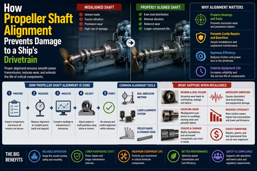

A ship’s propeller may be located far behind its main engine, yet the engine must transfer enormous amounts of power to that propeller continuously and reliably. Between the engine and the propeller is a long rotating system made up of shafts, couplings, bearings, seals, gearboxes, and supporting structures.
For this drivetrain to operate correctly, all of these components must be positioned so that the shaft rotates along a carefully controlled line.
This process is known as propeller shaft alignment. ⚙️🚢
If alignment is poor, the shaft can bend excessively, bearings can become overloaded, seals may wear prematurely, couplings can experience abnormal forces, and vibration can spread throughout the vessel. Over time, these problems may lead to expensive repairs or even a loss of propulsion.
Proper shaft alignment therefore does much more than simply make rotating parts “straight.” Marine engineers use alignment calculations to control how loads are distributed through the entire propulsion system under different operating conditions.
The goal is simple:
Transmit thousands of kilowatts of power from the engine to the propeller without forcing the shaft, bearings, or surrounding structure to carry damaging loads.
⚙️ What Is a Ship’s Propeller Shaft System?
A conventional marine propulsion system may contain several connected rotating components.
A simplified arrangement might look like:
Main engine → gearbox → intermediate shaft → stern tube shaft → propeller
Depending on the vessel, the system can also include:
- Flexible couplings
- Thrust bearings
- Line-shaft bearings
- Stern-tube bearings
- Seals
- Shaft brakes
- Power take-off equipment
The propeller shaft may extend many meters through the ship before reaching the propeller.
Large vessels can transmit tens of megawatts of mechanical power through this drivetrain.
Because the shaft is long and heavy, it does not behave like a perfectly rigid rod.
It bends under its own weight and under the loads created by the propeller, engine, bearings, and ship structure.
That flexibility is central to shaft-alignment engineering.
📏 Shaft Alignment Does Not Mean Perfectly Straight
A common misconception is that every bearing and shaft section should simply lie on one perfectly straight geometric line.
In reality, engineers often deliberately position bearings at slightly different elevations.
Why?
Because the shaft bends under load.
A long steel shaft supported at several locations behaves somewhat like a beam resting on multiple supports.
If every bearing were placed at exactly the same theoretical height without considering shaft deflection, some bearings might carry too much load while others carry almost none.
Therefore, alignment calculations determine a designed shafting curve.
The objective is to produce acceptable:
✅ Bearing reactions
✅ Shaft bending moments
✅ Coupling loads
✅ Gear loads
✅ Engine-flange loads
rather than merely making the shaft visually straight.
🧱 Bearings Carry the Shaft
The propeller shaft system is supported by bearings.
Typical bearings may include:
🌀 Line-shaft bearings
⚓ Stern-tube bearings
⚙️ Gearbox bearings
🚢 Engine bearings
Each bearing supports part of the shaft’s weight.
However, the load does not automatically divide evenly between them.
If one bearing is slightly too high, it may carry much more than its intended share.
A neighboring bearing may then become lightly loaded.
This can cause serious problems.
⚠️ What Happens When a Bearing Is Overloaded?
An overloaded bearing experiences excessive pressure between the rotating shaft and bearing surface.
This may result in:
🔥 Increased temperature
🛢️ Lubrication breakdown
🧱 Bearing material damage
📉 Reduced bearing life
⚙️ Shaft scoring
In oil-lubricated bearings, the shaft normally rides on a thin hydrodynamic oil film.
Excessive load can make that film too thin.
Metal-to-metal contact may then occur.
Once bearing surfaces begin overheating or wiping, damage can escalate quickly.
🌀 Lightly Loaded Bearings Can Also Be Dangerous
Too little bearing load can also create problems.
A shaft-bearing system is designed with an expected contact region.
If the shaft barely contacts a bearing, vibration or changing propeller forces may cause intermittent contact.
The shaft may repeatedly lift away and strike the bearing surface.
This can produce:
🔊 Noise
⚡ Impact loading
🧱 Local wear
📈 Vibration
Therefore, shaft alignment aims to keep bearing reactions within acceptable minimum and maximum ranges.
⚓ The Stern-Tube Bearing Is Particularly Important
The stern tube is the structure through which the propeller shaft passes as it exits the hull.
Inside it are bearings that support the shaft near the propeller.
The aft stern-tube bearing is especially important because it supports a large portion of the propeller and shaft load.
The propeller itself may weigh many tonnes.
It also generates hydrodynamic forces while rotating.
These loads act on the shaft near the aft bearing.
Improper alignment can concentrate pressure near one end of the bearing instead of distributing it over the intended length.
This phenomenon is often described as edge loading.
📐 What Is Bearing Edge Loading?
Imagine a shaft passing through a long cylindrical bearing.
Ideally, the shaft should contact the bearing in a controlled pattern.
If the shaft enters the bearing at an excessive angle, most of the load may be concentrated near one edge.
Instead of the entire bearing surface sharing the load, a small region carries much of it.
This can create:
🔥 Local overheating
🧱 Rapid wear
🛢️ Oil-film breakdown
⚙️ Bearing damage
Marine shaft-alignment studies therefore examine not only bearing reaction force but also the slope of the shaft through important bearings.
🌊 The Propeller Creates Dynamic Loads
The propeller does more than simply rotate.
As each blade travels through the water behind the ship, it encounters changing flow conditions.
Water velocity is not perfectly uniform around the propeller disk because the ship’s hull changes the wake.
As a result, propeller blades experience fluctuating forces.
These forces create:
↕️ Vertical loading
↔️ Horizontal loading
🔄 Torque fluctuations
📳 Vibration
The shaft transmits these dynamic forces into the bearings and hull.
Correct alignment ensures the drivetrain begins with a healthy static load distribution so it can better tolerate these changing forces during operation.
💪 Propeller Thrust Adds Another Major Load
The propeller pushes water backward.
The reaction force pushes the ship forward.
This produces axial thrust along the shaft.
A dedicated thrust bearing transfers this force from the rotating shaft into the ship structure.
On large vessels, the thrust force can be enormous.
The propulsion shafting therefore experiences:
Torque + bending + axial thrust
simultaneously.
Alignment must be compatible with all three.
🔩 Misalignment Can Damage Couplings
Shaft sections are often joined using rigid or flexible couplings.
A rigid coupling expects the connected shafts to meet with very small angular and positional differences.
Poor alignment can create:
🔩 Excessive bolt loads
📐 Angular stress
⚙️ Flange bending
📳 Vibration
💥 Fatigue cracking
Coupling bolts may be subjected to repeated cyclic loads that were never intended by the design.
Over millions of revolutions, even moderate additional stress can contribute to fatigue damage.
⚙️ Gearboxes Are Sensitive to Shaft Alignment
Many ships use reduction gearboxes between the engine and propeller shaft.
The gearbox converts high engine speed into lower propeller speed while transmitting large torque.
Gear teeth must mesh accurately.
If external shaft loads distort the gearbox casing or bearings, gear contact patterns can change.
This may cause:
🔊 Gear noise
🔥 Higher temperatures
⚙️ Tooth wear
🛢️ Lubrication problems
Shaft alignment calculations therefore often include allowable gearbox-bearing and flange loads.
The propulsion system must be considered as one connected structure.
🏭 Main Engines Can Also Be Affected
On directly driven vessels, the propeller shaft may connect closely to the engine crankshaft.
Large low-speed marine diesel engines have long crankshafts supported by multiple main bearings.
The shafting system can influence the load at the engine’s aft end.
If alignment is incorrect, excessive bending moment may be transferred into the engine.
Potential consequences include:
⚠️ Uneven main-bearing loads
📐 Crankshaft distortion
🧱 Bearing wear
🔧 Coupling problems
Engine manufacturers therefore specify permissible shafting loads at the engine flange.
🌡️ Alignment Changes When the Ship Warms Up
One of the most challenging aspects of marine alignment is that the ship does not remain in the same condition.
When the vessel is cold in a shipyard, machinery foundations have one temperature.
After hours of operation:
🔥 The engine heats up
⚙️ Gearboxes warm
🛢️ Lubricating oil temperature rises
🌡️ Bearings expand
🏗️ Foundations change slightly
This thermal growth changes component positions.
An engine may rise slightly relative to a cold reference point.
The shaft alignment measured during installation must therefore account for expected operating temperature.
🚢 Hull Deflection Changes Shaft Alignment
Ships are flexible structures.
A large vessel can bend slightly as:
🌊 Waves pass underneath
📦 Cargo distribution changes
⛽ Fuel is consumed
💧 Ballast tanks are filled or emptied
This is known as hull deflection.
The engine, shaft bearings, and stern tube are attached to the hull.
If the hull changes shape, their relative positions change too.
Therefore, an alignment that is perfect in dry dock may not remain identical when the ship is afloat and fully loaded.
⚓ Dry-Dock and Afloat Conditions Are Different
During construction or repair, a vessel may sit on blocks in dry dock.
The hull is supported from underneath.
Once floated, buoyancy supports the hull differently.
That change in structural loading can alter the position of shaft bearings.
Engineers therefore account for the difference between:
🏗️ Dry-dock alignment
and:
🌊 Afloat operating alignment.
For large or flexible vessels, the difference can be significant.
📦 Loading Condition Matters
Consider a cargo ship.
When empty, its hull experiences one bending condition.
When fully loaded, the hull may deflect differently.
Fuel consumption during a voyage can further change weight distribution.
This means shaft alignment may be evaluated under several vessel conditions, such as:
- Ballast condition
- Full-load condition
- Partial-load condition
- Hot operating condition
The design must remain acceptable across the expected operating envelope.
🧮 How Engineers Calculate Shaft Alignment
Marine engineers model the shaft as a flexible beam supported by bearings.
The model includes:
📏 Shaft dimensions
⚙️ Material stiffness
🪨 Component weights
🌀 Bearing locations
🚢 Propeller mass
📐 Bearing offsets
🔩 Coupling stiffness
Computer programs can then calculate:
- Shaft deflection
- Bearing reactions
- Bending moments
- Shear forces
- Shaft slopes
- Coupling loads
Engineers adjust bearing positions until all important values fall within acceptable limits.
📊 Bearing Reaction Is a Key Result
A bearing reaction is the force a bearing applies to support the shaft.
Suppose a shaft has four bearings.
The calculated loads might be:
Bearing 1: 120 kN
Bearing 2: 180 kN
Bearing 3: 95 kN
Bearing 4: 250 kN
Engineers compare these values with design limits.
If one bearing is overloaded, its vertical offset may be adjusted.
Changing one bearing position also affects nearby bearings.
This makes shaft alignment an interconnected optimization problem.
📐 Bearing Offset Is Used to Tune Alignment
A bearing may intentionally be installed slightly above or below a common reference line.
This small vertical displacement is called a bearing offset.
Moving a bearing upward tends to increase its load.
Moving it downward tends to reduce its load.
Even adjustments of fractions of a millimeter can noticeably change reaction forces in large shafting systems.
This demonstrates how precise marine alignment must be.
🔍 How Shaft Alignment Is Measured During Installation
Engineers and technicians use several methods to establish and verify shaft alignment.
These may include:
🔦 Optical alignment
📡 Laser alignment
📏 Dial indicators
🧰 Mechanical gauges
🧵 Wire alignment techniques
📊 Bearing-load measurements
The exact method depends on the vessel, equipment, and construction stage.
Modern laser systems can measure extremely small angular and positional differences between coupling faces.
📡 Laser Alignment Improves Precision
Laser shaft-alignment equipment uses sensors mounted on the shaft or coupling.
The system measures relative offset and angular misalignment as the shafts are rotated.
Software can then calculate how much machinery must be moved.
For example:
Move gearbox 0.30 mm upward
or:
Shift motor 0.20 mm toward port
This reduces guesswork and allows extremely precise adjustments.
📏 Dial Indicators Remain Useful
Traditional dial indicators are still widely used.
A dial indicator can measure tiny changes in distance as shafts or couplings are rotated.
Technicians may use methods such as:
- Rim-and-face measurement
- Reverse-dial measurement
- Coupling sag checks
These techniques require careful setup and correction for measurement errors, but they remain reliable when properly performed.
🧪 Jack-Up Tests Measure Bearing Load
One important marine technique is the jack-up test.
A hydraulic jack is placed beneath the shaft near a bearing.
The shaft is slowly lifted while load and displacement are measured.
From the resulting relationship, engineers estimate the bearing reaction.
This provides a direct way to compare actual bearing loading with the calculated alignment model.
Jack-up tests are often used during commissioning or major maintenance.
📈 Why Measurement Must Match the Model
A computer alignment calculation is only useful if the real ship matches the assumed geometry.
Installation tolerances, weld distortion, foundation movement, and machining differences can all affect actual positions.
Engineers therefore compare:
Calculated bearing reactions
with:
Measured bearing reactions
If the results differ substantially, they investigate why.
The model may then be updated to better represent the actual vessel.
🔧 Alignment Changes During Maintenance
Shaft alignment is not only a shipbuilding issue.
Major maintenance can change drivetrain geometry.
Examples include:
⚙️ Replacing a gearbox
🌀 Renewing stern-tube bearings
🔩 Removing shaft sections
🛢️ Changing bearing materials
🏭 Overhauling the main engine
After such work, alignment may need to be rechecked.
Even removing and reinstalling a heavy machine can change its final position by fractions of a millimeter.
🧱 Foundation Settling Can Alter Alignment
Machinery sits on foundations attached to the hull.
Over years of service, foundations can experience:
- Structural deformation
- Corrosion
- Bolt relaxation
- Chock deterioration
- Local settling
These changes may slowly shift machinery position.
A drivetrain that was perfectly aligned at commissioning can therefore drift out of alignment over time.
Periodic monitoring helps detect this before damage becomes severe.
📳 Vibration Can Be a Warning Sign
Misalignment can generate abnormal vibration.
Possible symptoms include:
📳 Elevated shaft vibration
🔊 Unusual bearing noise
🔥 Rising bearing temperature
🛢️ Lubricant contamination
⚙️ Coupling wear
However, vibration alone does not prove alignment is the cause.
Propeller cavitation, imbalance, damaged bearings, gear faults, and engine excitation can produce similar symptoms.
Engineers use vibration analysis alongside temperature, oil analysis, alignment measurements, and operating data to diagnose the true problem.
🌡️ Bearing Temperature Is Closely Monitored
Marine propulsion bearings often have temperature sensors.
If a bearing begins carrying excessive load, friction and oil-film conditions may worsen.
Temperature can rise.
An alarm may warn the crew before catastrophic damage occurs.
Monitoring systems may track:
🌡️ Bearing metal temperature
🛢️ Oil temperature
📳 Vibration
⚙️ Shaft speed
Trend data is especially useful.
A bearing that slowly becomes hotter over months may indicate developing alignment or lubrication problems.
🛢️ Lubrication and Alignment Are Closely Connected
Bearings depend on proper lubrication.
In hydrodynamic bearings, shaft rotation drags oil into a converging gap and creates a pressure film.
This oil film separates the shaft from the bearing surface.
Poor alignment can distort the contact pattern.
Instead of a healthy pressure distribution, the oil film may become extremely thin at one edge.
Thus, even a high-quality lubricant cannot fully compensate for severe misalignment.
Good lubrication and correct alignment must work together.
🌀 Shaft Whirling and Vibration Must Be Considered
A rotating shaft has natural vibration modes.
At certain rotational speeds, excitation can interact with these modes.
This may produce whirling or resonant vibration.
Alignment affects bearing stiffness and support conditions, which can influence these dynamics.
Propulsion designers therefore evaluate not only static alignment but also:
📳 Lateral vibration
🔄 Torsional vibration
↔️ Axial vibration
A safe drivetrain must perform well dynamically as well as statically.
🔄 Torsional Vibration Is Different From Alignment
Torsional vibration occurs when the shaft twists back and forth slightly as torque fluctuates.
Diesel-engine firing pulses and propeller loads can excite this motion.
Shaft alignment mainly concerns bending and support geometry, but the overall drivetrain design must account for both.
A propulsion system could be perfectly aligned yet still experience dangerous torsional resonance.
Marine engineers therefore perform separate analyses for different vibration modes.
🪶 Flexible Couplings Can Absorb Small Misalignments
Some propulsion systems use flexible couplings.
These components can accommodate limited:
📐 Angular misalignment
↔️ Axial movement
📏 Radial offset
They can also reduce transmission of vibration.
However, flexible couplings do not eliminate the need for proper alignment.
Every coupling has limits.
If engineers intentionally rely on a flexible coupling to compensate for severe installation errors, the coupling can overheat or fail prematurely.
🌊 Water-Lubricated Bearings Have Different Behavior
Not every stern-tube bearing uses oil.
Some vessels use water-lubricated bearings made from engineered polymers, rubber-like materials, or composite structures.
Seawater provides lubrication.
These systems can reduce the risk of oil leakage into the marine environment.
However, bearing clearances, loading, material behavior, and alignment requirements differ from conventional oil-lubricated systems.
The shaft must still maintain appropriate contact and load distribution.
🌱 Environmental Regulations Influence Shafting Design
Traditional stern tubes may contain lubricating oil.
If seals fail, oil can leak into seawater.
Environmental concerns have encouraged increased use of:
🌊 Water-lubricated bearings
🌱 Environmentally acceptable lubricants
🔧 Improved seal systems
Changes to bearing or lubricant technology can influence shaft-alignment calculations because bearing stiffness and operating behavior may change.
🔒 Stern-Tube Seals Depend on Proper Shaft Position
Where the rotating shaft passes through the hull, sealing systems prevent seawater from entering the ship and lubricant from escaping.
A misaligned shaft can create excessive radial movement at the seal.
This may lead to:
💧 Water ingress
🛢️ Oil leakage
🔥 Seal wear
🔧 Frequent maintenance
Alignment therefore protects not only bearings and couplings but also the vessel’s shaft-sealing system.
⚓ Propeller Weight Changes During Operation
The propeller is supported partly by the stern-tube bearings.
But while the propeller rotates underwater, hydrodynamic forces can modify the effective loading.
The operating shaft condition may therefore differ from the static condition measured while stopped.
Advanced alignment studies may consider hydrodynamic propeller forces when evaluating aft bearing performance.
This is especially important for very large propellers.
🚢 Ships With Long Shaft Lines Need Extra Care
Some vessels have relatively short propulsion shaft systems.
Others may have long shaft lines with several intermediate bearings.
Longer systems are generally more sensitive to:
📐 Bearing offsets
🏗️ Hull deformation
🌡️ Thermal growth
📦 Loading changes
A small movement at one bearing can redistribute loads across many others.
This makes accurate modeling and measurement especially important.
⚙️ Alignment in Twin-Screw Ships
Some ships use two independent propulsion shafts.
Each shaft drives its own propeller.
The port and starboard shaft lines may experience slightly different structural conditions depending on hull geometry and machinery arrangement.
Each drivetrain therefore requires its own alignment analysis.
Twin-screw vessels also have more bearings, seals, and coupling systems to monitor.
🔋 Hybrid and Electric Propulsion Still Requires Alignment
Modern ships increasingly use:
⚡ Electric motors
🔋 Battery systems
🧠 Hybrid propulsion
⚙️ Integrated electric drives
Replacing a diesel engine with an electric motor does not eliminate mechanical alignment requirements if a conventional shaft and propeller remain.
The motor bearings and couplings still need to interact correctly with the shaft line.
In some cases, electric motors operate at higher rotational speeds and use reduction gears, creating additional alignment considerations.
🛳️ Podded Propulsion Changes the Problem
Some ships use podded propulsion units in which the electric motor and propeller are integrated into an external rotating pod.
This eliminates the traditional long internal propeller shaft.
However, pod systems introduce their own bearing, seal, structural, and alignment requirements.
The broader principle remains the same:
Rotating machinery must be supported so forces remain within the limits of bearings and structures.
💰 Why Proper Alignment Saves Money
Correct shaft alignment improves lifecycle economics.
Benefits can include:
✅ Longer bearing life
✅ Reduced seal wear
✅ Fewer coupling problems
✅ Lower vibration
✅ Reduced unplanned downtime
✅ Less emergency repair work
A propulsion failure can be extraordinarily expensive.
A commercial ship that cannot sail may lose revenue every day while waiting for parts or dry-dock access.
Preventing alignment-related damage is therefore both an engineering and economic priority.
🧰 Signs That Alignment May Need Investigation
Possible warning signs include:
🔥 Repeated bearing overheating
📳 Unusual vibration
🛢️ Rapid seal leakage
🔩 Coupling wear
⚙️ Gear contact problems
📉 Abnormal bearing-load measurements
These symptoms do not automatically prove misalignment, but they justify investigation.
Engineers may then perform:
- Laser alignment
- Jack-up testing
- Shaft-deflection measurements
- Vibration analysis
- Bearing inspection
A combination of methods provides the strongest diagnosis.
📊 Digital Monitoring Is Improving Shaft Alignment Management
Modern vessels increasingly collect continuous machinery data.
Sensors can monitor:
🌡️ Bearing temperature
📳 Vibration
⚙️ Torque
🔄 Shaft speed
📐 Shaft position
These data can be analyzed over time.
Instead of discovering a problem only after a bearing fails, operators may detect gradual changes in behavior.
Advanced condition-monitoring systems can compare actual measurements with expected operating patterns.
This creates opportunities for predictive maintenance.
🤖 The Future of Marine Shaft Alignment
Future propulsion systems may increasingly use:
📡 Real-time shaft-position sensors
🧠 Digital twins
📊 Automated bearing-load estimation
🤖 Predictive analytics
🌡️ Thermal-growth modeling
A digital twin could combine ship loading, temperature, shaft speed, and sensor data to estimate how bearing reactions change during a voyage.
Engineers could then identify unfavorable alignment conditions before physical damage occurs.
This would transform alignment from a mainly installation-time activity into a continuously monitored aspect of propulsion health.
✅ Conclusion
Propeller shaft alignment protects a ship’s drivetrain by ensuring that the long rotating shaft system is supported in a carefully controlled way.
The goal is not to force every component onto one perfectly straight geometric line. Instead, engineers account for shaft flexibility, propeller weight, bearing positions, hull deflection, thermal growth, gearbox loads, engine loads, and operating conditions to create an acceptable distribution of forces throughout the drivetrain. ⚙️🚢
If alignment is poor, one bearing may become overloaded while another carries too little load. The stern-tube bearing may suffer edge loading, oil films can break down, couplings may experience excessive bending, seals can wear, and gearbox or engine bearings may receive damaging forces.
Proper alignment helps prevent these problems by controlling:
📐 Shaft deflection
⚓ Bearing reaction forces
🔩 Coupling loads
🔥 Bearing temperatures
📳 Vibration
🛢️ Lubrication conditions
Engineers verify the system using alignment calculations, laser measurements, dial indicators, jack-up tests, vibration monitoring, and bearing-temperature data.
Most importantly, alignment must remain acceptable not only during installation but also when the vessel is afloat, fully loaded, heated to operating temperature, and exposed to changing sea conditions.
The principle is fundamental:
A propeller shaft can transmit enormous power reliably only when every bearing and connected machine supports it in the way the system was designed to expect. 🚢⚙️✅
By controlling those loads, shaft alignment helps ships avoid premature bearing failures, damaged seals, gearbox problems, excessive vibration, and costly propulsion breakdowns—keeping the vessel moving safely and efficiently across thousands of operating hours.