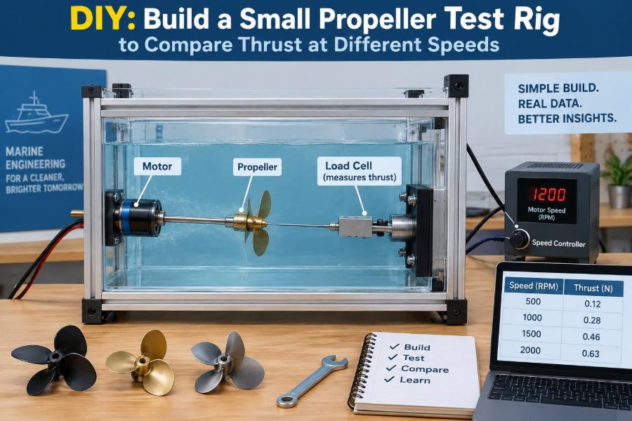

A small model propeller can look deceptively simple: apply power, see it turn, and watch water move. Yet the moment you compare two propellers—or run the same propeller at two speeds—you meet the practical questions that drive real marine propulsion work.
Which setup produces more useful push? Does a larger propeller always help? Why can a motor draw more current without delivering a proportionate increase in thrust? A compact bench rig cannot answer every hydrodynamic question, but it can make those questions visible.
This project builds a modest, guarded water test rig that measures static thrust, the pulling or pushing force produced while the rig remains stationary. With careful testing, it also lets you compare performance across controlled shaft speeds.
The goal is not to reproduce a ship’s open-water trial in a bucket. It is to learn sound experimental practice: isolate a variable, measure it honestly, record uncertainty, and understand where a result applies—and where it does not.
🧭 What This Rig Can Teach You
A propeller test rig turns propulsion theory into direct observation. You can compare blade diameter, pitch, blade count, rotation rate, and motor input while measuring the resulting force.
For students, it is an approachable introduction to thrust, torque, electrical power, and data quality. For working professionals, it is a useful reminder that an instrument reading is meaningful only when the test condition is defined.
At its simplest, the rig measures a force in newtons or grams-force. The more valuable result is usually the trend: for example, whether thrust rises steadily with speed, levels off, or becomes erratic because of ventilation or cavitation-like effects.
⚓ Static Thrust Versus Propeller Performance Underway
Static thrust is measured with no incoming flow past the propeller. The propeller accelerates relatively still water aft, and the reaction force is transmitted through the motor mount to the scale or load cell.
A moving vessel operates differently. As the hull advances, water approaches the propeller plane at an advance speed. This changes blade inflow angle, loading, efficiency, and the amount of thrust needed to overcome hull resistance.
Your rig therefore measures a bollard-pull-style condition, not full open-water propeller efficiency. It remains useful for low-speed manoeuvring comparisons, model-boat experimentation, and basic demonstrations, but it should not be used to predict a vessel’s top speed.
📐 The Core Physics in Plain Language
A propeller creates a pressure difference between its blade faces and changes the momentum of water. The water leaves the propeller region with a rearward velocity component; the equal-and-opposite reaction acts as forward thrust on the propeller shaft and its support.
Thrust is commonly represented by T. A simple force measurement gives T directly. Shaft power is related to torque and rotational speed, while electrical input power is approximately voltage multiplied by current.
Electrical power is not identical to shaft power. Losses occur in wiring, the motor, couplings, bearings, and electronic speed control. That distinction is one reason a rig should record both force and electrical conditions rather than treating current alone as a measure of propulsion quality.
🧮 Why Rotational Speed Matters So Much
For a geometrically similar propeller operating in comparable conditions, thrust is often approximated as scaling with the square of rotational speed. In simplified form, doubling revolutions per second can raise thrust by roughly four times.
Real bench tests rarely follow that relationship perfectly. Water recirculation, motor heating, supply voltage drop, surface effects, and changing blade conditions all influence the result.
That is precisely why measured data is educational. The approximate square-law expectation provides a reference, while deviations encourage you to investigate the physical cause rather than assume the equipment is wrong.
🧰 Choose a Sensible Scope Before Buying Parts
A safe first rig uses a low-voltage DC motor, a small commercial plastic propeller, and a rigid container of water. Aim for controlled comparison, not maximum thrust.
A practical setup can be built around:
- a nonconductive water container large enough to keep the propeller clear of walls and bottom;
- a motor and shaft arrangement mounted above the waterline;
- a sliding carriage or pivoted frame that transfers axial force to a scale;
- a low-voltage power supply, fuse, switch, and speed controller;
- an optical or magnetic tachometer, if available;
- a digital kitchen scale, luggage scale, or preferably a suitably rated load cell.
A smaller rig is easier to guard, drain, and repeat. Its limitation is that wall and surface effects become more influential, so dimensions and clearances must be recorded.
🛒 Parts That Make Measurement Easier
Use components that can be secured rather than hand-held. A brushed DC motor is straightforward for introductory work, while a brushless motor and electronic speed controller can offer a wider operating range but require more careful setup.
Choose a shaft coupler with minimal runout, meaning it does not make the shaft orbit as it turns. A bent shaft or poorly aligned coupler causes vibration, unreliable force readings, and an avoidable mechanical hazard.
| Component | Purpose | Useful selection note |
|---|---|---|
| Rigid frame | Holds motor and transmits thrust | Should not flex noticeably under expected load |
| Scale or load cell | Measures axial force | Use a range well above expected thrust |
| Tachometer | Measures shaft rotational speed | Measure actual shaft speed, not a controller setting |
| Current meter | Shows electrical loading | Place it safely in series with the supply |
| Guard and splash shield | Limits contact and spray | Must not obstruct the propeller inflow |
🧱 Build a Frame That Measures Force, Not Flex
The central mechanical task is to make the propeller assembly free to move only along the thrust axis. If the motor bracket bends or rubs against the frame, some thrust disappears into friction or elastic deformation instead of reaching the measuring device.
A simple approach is a carriage running on two smooth, parallel guides. The motor is attached to the carriage, and a rigid link connects the carriage to the scale. The scale is fixed to the base.
Another option is a pivoted arm with a known lever geometry. This can work well, but its angle changes as thrust rises and may alter the force transmitted to the scale. A straight-line carriage is generally easier for a first build.
🧲 Arrange the Load Path Correctly
Imagine the thrust force traveling from the propeller through the shaft, motor bearings, motor case, bracket, carriage, linkage, and finally into the scale. Every item in that chain must be aligned with the propeller shaft as closely as practical.
Side loading introduces friction and can make readings depend on whether the carriage approached a point from the left or right. A flexible string can remove some side load, but it also permits swinging; a light, straight linkage is usually better.
Before filling the tank, push and pull the carriage gently by hand. It should move smoothly, return consistently, and produce nearly the same scale reading for the same applied position.
🌊 Select a Tank With Enough Clearance
A transparent storage tote or aquarium-style vessel makes the flow visible, but acrylic and glass require careful handling. The tank must be stable, supported over its full base, and large enough that the propeller does not operate close to a wall.
As a practical starting principle, provide several propeller diameters of clearance downstream where possible, plus generous side and bottom clearance. A small tank causes the accelerated water to strike boundaries, recirculate, and return toward the propeller.
Those effects do not make the test worthless; they make it a test of a propeller in that tank arrangement. Report the geometry so another person understands the limitation.
💧 Set Propeller Depth and Orientation
Mount the shaft horizontally and place the propeller sufficiently below the free surface that it does not draw air down from above. Keep the hub, blades, and shaft line clear of the tank floor.
A propeller near the surface may ventilate: air is drawn into the blade region, reducing the density of fluid being accelerated and producing unstable thrust. Ventilation is often visible as a frothy vortex and heard as a sudden change in motor note.
Mark the mounting height on the frame. Depth is a test variable, so it must remain fixed during a speed comparison.
🔌 Keep Electricity Away From Splash Zones
Water and electrical equipment demand conservative design. Keep mains-powered equipment away from the tank, use a low-voltage supply at the rig, and arrange a drip loop in every cable so water cannot run toward connectors.
Use an appropriately rated fuse close to the power source. Fit a clearly reachable switch or emergency disconnect, and do not adjust wiring, propellers, or couplings while the system is energized.
Battery packs can supply high fault currents even at low voltage. Insulate exposed conductors, avoid damaged cells, and follow the manufacturer’s charging and handling guidance. If you are uncertain about wiring, ask a qualified person to review the setup.
🛡️ Guard the Rotating Parts
A small propeller can cut skin, throw a damaged blade fragment, or snag loose clothing. Install a rigid guard around the exposed coupling and upper shaft, while leaving the propeller’s water inflow and discharge reasonably unobstructed.
Keep hands clear of the tank during operation. Tie back hair, remove dangling lanyards, and wear eye protection when first commissioning a new shaft, coupler, or propeller.
Stop immediately if vibration increases, a blade appears damaged, the motor mount loosens, or the tank shifts. A test rig is successful only when it produces repeatable data without asking the operator to take casual risks.
⚖️ Pick a Force Sensor You Can Understand
A digital kitchen scale may be sufficient for a low-thrust educational rig if it has adequate resolution and can be arranged to read the force direction correctly. Some scales behave poorly when loaded sideways or dynamically, so test its response before relying on it.
A hanging luggage scale can work when the rig pulls in tension. A load cell with an amplifier and data logger offers better possibilities for time-resolved measurements, but it needs calibration, stable mounting, and protection from water.
Whichever instrument you use, know whether it reads mass units or force units. A display in grams is often interpreted as gram-force in this context; for engineering calculations, convert to newtons using the local gravitational acceleration as appropriate.
✅ Zero and Calibrate Before Each Session
Zero the instrument with the complete stationary carriage installed, cables arranged, and no propeller thrust. This removes the effect of the assembly’s resting force on the sensor.
Check calibration using known masses or a known applied load in the same direction as the test force. A sensor that reads correctly when pressed vertically may not be accurate when pulled horizontally through an improvised linkage.
Do not expect laboratory-grade certainty from household equipment. Record the scale resolution, the calibration check, and any observed scatter. Honest uncertainty is more valuable than a precise-looking number with no supporting method.
🔄 Verify Rotation Direction Before Submerging
Most propellers are designed for a particular rotation direction. Check the manufacturer’s marking or inspect the blade shape: reversing rotation usually produces much lower thrust and may overload the motor.
Briefly run the motor at low speed in air only long enough to confirm direction and observe shaft smoothness. Then disconnect power before changing anything.
Once submerged, begin at the lowest controllable speed. This reduces splash, gives you time to spot an unstable carriage, and prevents an unexpected high-current start from tripping or damaging the supply.
📏 Measure Actual RPM Rather Than Controller Position
A speed-control knob marked from zero to ten does not measure revolutions per minute. Motor speed changes with supply voltage, load, heating, and propeller condition.
An optical tachometer can read reflective tape on a dry, guarded section of shaft or coupling. A Hall-effect sensor and magnet can also work, provided the magnet is secure and the sensor arrangement does not disturb the mechanics.
If direct RPM measurement is unavailable, record supply voltage and a repeatable controller setting, but label the result accordingly. Do not describe it as a speed-based comparison when speed was not measured.
📝 Create a Test Sheet Before Turning Anything On
Good experiments are planned before data appears. Prepare a table with columns for propeller identification, diameter, pitch if known, immersion depth, test number, RPM, voltage, current, thrust, water temperature, and observations.
Observations matter. Note visible air ingestion, splashing, vibration, motor noise, changes in water circulation, and whether the scale reading was steady or fluctuating.
Use the same sample interval and settling time for every point. A written sequence reduces the temptation to make informal adjustments only when a result looks surprising.
▶️ Follow a Repeatable Test Sequence
- Inspect fasteners, guards, wiring, tank level, and sensor zero.
- Set the propeller depth and confirm the carriage moves freely.
- Start at low power and allow the flow and reading to settle.
- Record RPM, thrust, voltage, current, and relevant observations.
- Increase to the next planned speed and repeat without changing geometry.
- Reduce power gradually, stop, and inspect the rig before changing propellers.
At each speed, take multiple readings rather than trusting a single value. If readings differ widely, investigate the source before calculating an average. Repetition cannot fix a systematic problem such as rubbing linkage or a ventilating propeller.
📊 Repeat Runs and Treat Scatter as Information
For a basic comparison, three or more runs at each condition often reveal whether the rig is behaving consistently. Calculate a simple mean, then look at the spread between readings.
A narrow spread suggests stable operation, although it does not prove accuracy. A wide spread may reveal turbulent recirculation, fluctuating electrical supply, sensor vibration, temperature change, or operator timing differences.
When reporting, use sensible precision. If thrust readings wander by several tenths of a newton, reporting values to three decimal places implies a confidence the apparatus does not possess.
📈 Plot Thrust Against RPM
A graph of thrust on the vertical axis and RPM on the horizontal axis is the clearest first result. Plot every repeated run if possible, or show the average with a visible range or error indication.
The curve will usually rise with speed. Look for a changing slope, sudden jumps, or a plateau. These features are prompts for physical inspection: perhaps the motor voltage sagged, the propeller began ventilating, or the small tank’s return flow became dominant.
For propeller comparison, use the same RPM values whenever possible. Comparing one propeller at the same controller setting is less informative because each propeller may spin at a different speed under load.
🔋 Record Current Without Confusing It With Thrust
Current is a useful indicator of motor load. At approximately constant voltage, higher current means greater electrical input power, but it does not automatically mean a better propeller.
One propeller might deliver more thrust while drawing considerably more current. Another might offer less static thrust but potentially better efficiency at a relevant advancing speed—something this stationary rig cannot establish by itself.
A helpful comparison is thrust per electrical watt, calculated cautiously as thrust divided by measured voltage times current. Call it an electrical-input comparison, not propeller efficiency, because motor and controller losses remain included.
🌡️ Control Temperature and Supply Conditions
Water viscosity changes with temperature, and motor resistance rises as the motor warms. Over a short student test these effects may be small compared with other uncertainties, but long sessions can drift noticeably.
Use approximately the same water temperature for comparative runs, allow the motor to cool if it becomes hot, and measure voltage at the rig rather than only at a distant power supply display.
A battery that discharges over a session can change both RPM and thrust. Either use a stable current-capable supply or log voltage continuously and interpret later points with care.
🌀 Recognize Ventilation and Cavitation Carefully
Ventilation is the ingestion of atmospheric air, usually from the free surface. It is common in shallow model tests and often causes obvious bubbles, unstable force, and reduced thrust.
Cavitation is different: local pressure falls enough for vapor-filled cavities to form in the water. It depends on blade loading, geometry, water conditions, depth, and rotational speed. It cannot be diagnosed reliably from noise alone.
Do not label every bubble trail as cavitation. On a small open tank rig, surface ventilation and recirculated air are usually more immediate explanations. If cavitation assessment is the goal, the experiment requires more controlled conditions than this introductory apparatus provides.
🏊 Understand Tank Walls and Recirculating Flow
Propeller discharge moves water downstream until it reaches a wall, where it turns and eventually returns toward the propeller. In a confined tank, the propeller may ingest water that it has already accelerated and disturbed.
This can alter thrust, cause unsteady loading, and make results dependent on run duration. A short reading after stabilization may differ from a reading taken after the entire tank has developed a strong circulation pattern.
Keep the timing consistent. If possible, observe the flow with harmless suspended visual markers appropriate to the water system, but do not add particles that can damage the pump, foul the propeller, or change water properties significantly.
🔧 Compare Propeller Diameter, Pitch, and Blade Count
Diameter sets the size of the disc sweeping through water. At a given RPM, a larger diameter generally acts on more water and can produce more thrust, but it also requires more torque and may overheat or overload the motor.
Pitch is the theoretical forward distance per revolution in an ideal solid medium. Higher pitch can suit higher advance speeds, but in static conditions it may load the motor heavily without giving the expected advantage.
More blades can increase blade area and smooth loading, but also introduce additional drag and interaction effects. There is no universal “best” propeller: suitability depends on motor torque, operating speed, vessel resistance, depth, and the objective of the craft.
🧪 Change Only One Variable at a Time
If you replace the propeller, change the immersion depth, move the motor mount, and use a different battery in the same session, the result cannot identify the cause of any difference.
Hold all conditions constant except the variable under investigation. For example, compare two propellers of different pitch at the same diameter, depth, shaft location, RPM points, and water condition.
When a new propeller requires a different motor setting to achieve the same RPM, that is expected. The motor setting is not the controlled variable; measured RPM is.
🚫 Common Build Mistakes and Their Fixes
- Reading thrust while the mount touches the tank: add clearance so the force reaches the sensor.
- Using a flexible wooden strip as the only frame: reinforce it or use a stiffer structure to reduce bending.
- Testing close to the free surface: lower the propeller and check for surface vortices.
- Ignoring shaft vibration: realign the coupling and replace damaged propellers before collecting data.
- Making long full-power runs: use short, consistent test windows and monitor motor temperature.
- Comparing readings from different water levels: mark and restore the same fill level for every run.
Most poor results are not failures of theory. They are reminders that a measurement system includes mechanics, instruments, power supply, fluid boundaries, and operator procedure.
🧾 Present Results Like an Engineer
A concise test report should state what was tested, how thrust was measured, and the conditions that define the result. Include a photograph or sketch in your own documentation showing the force path and tank geometry.
Report propeller dimensions and material when known, motor and supply type, immersion depth, measurement ranges, RPM method, number of repeats, and notable limitations. Give raw readings or a clear summary rather than only a polished graph.
A strong conclusion might say: “Under this rig’s static, shallow-tank conditions, Propeller A produced greater measured thrust than Propeller B at matched RPM, but also drew greater current.” That claim is specific, useful, and does not overextend to vessel performance at sea.
🎓 Extensions for Deeper Investigation
Once the basic rig is repeatable, add complexity gradually. A data logger can capture force and current during startup transients. A temperature probe can document water and motor conditions.
You can also investigate:
- the effect of propeller submergence on ventilation onset;
- thrust changes from a nozzle or duct, while noting its own drag and blockage effects;
- differences between clockwise and counterclockwise propellers of equivalent geometry;
- the effect of shaft angle, which is relevant to many small craft installations;
- how force changes over time as tank recirculation develops.
Each extension needs a revised method. More sensors create more opportunities for error, so improve the test plan at the same pace as the equipment.
🌍 Know When a Larger-Scale Test Is Needed
A compact rig cannot model hull-propeller interaction, wake fraction, thrust deduction, sea state, cavitation margins, structural vibration, or full-scale engine matching. It also cannot directly measure useful propulsive power without a representative advance flow.
For more realistic propeller characterization, engineers use towing tanks, circulating water channels, cavitation tunnels, instrumented model tests, and validated computational methods. Each approach has assumptions, cost, and scale effects to manage.
The small rig still has a legitimate role: it develops intuition, screens simple alternatives, demonstrates trends, and teaches why controlled conditions matter before high-consequence decisions are made.
🧠 The Core Lesson From a Small Test Rig
The propeller is only one part of the experiment. The frame determines whether force reaches the sensor, the tank affects the water entering the blades, the power system affects RPM, and the procedure determines whether results can be compared.
Build for rigidity, alignment, guarding, and repeatability. Measure actual RPM and electrical conditions, repeat each point, and describe static-tank limitations plainly.
The most useful result is not the largest thrust number; it is a trustworthy comparison tied to clearly defined test conditions.
With that mindset, a small propeller rig becomes more than a DIY project. It becomes a compact lesson in marine engineering: turn a physical question into a controlled measurement, then let the evidence—along with its limits—guide the conclusion. 🚢⚙️🌊