Problem Definition: Package lifting device
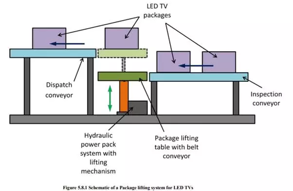
For a dispatch station of a LED TV production house, design a package lifting device to lift packages containing 21” to 51” LED TVs from the inspection conveyor to the dispatch conveyor. Draw the hydraulic circuit diagram. List the components. Readers are requested to assume suitable data.
Solution
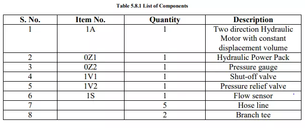
By applying the principle of hydraulics and after studying the various sensors, pumps, valves and hydraulic actuators, the proposed hydraulic circuit is shown in Figure 5.8.1. Components required are listed in table 5.8.1.
Proposed hydraulic circuit and its operation
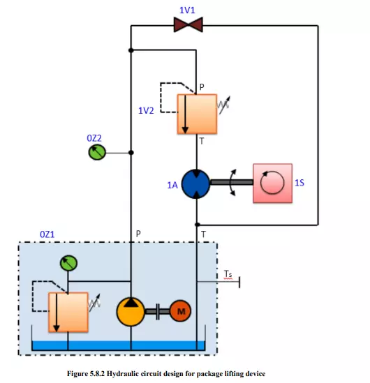
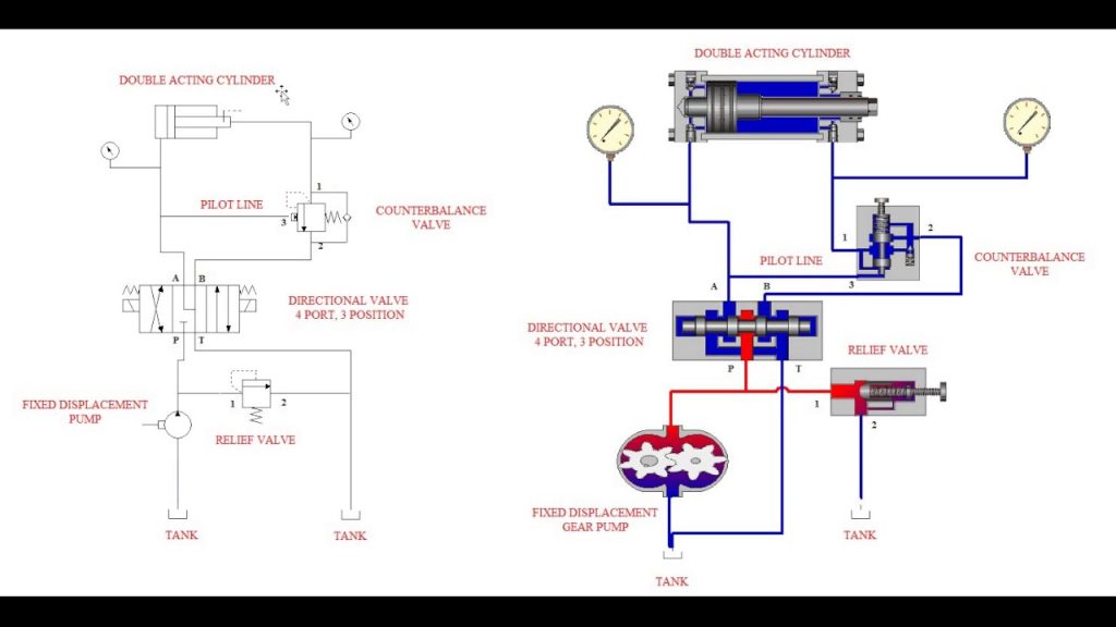
Figure 5.8.2 shows the circuit design for package lifting device. The two direction hydraulic motor is run by using a hydraulic power pack. Required valves and pressure sensors are also included for desired control action. Readers are requested to carefully read the circuit and comprehend the circuit.
Once the hydraulic circuit has been assembled and checked, valve 1V1 and pressure relief valve 1V2 can be operated in sequence to obtain the rotary motion of hydraulic motor in required direction (clockwise/counter clockwise). This rotary motion can further be converted into linear motion by using suitable motion converter mechanism viz. Rack and pinion mechanism. Linear motion is used to lift the packages. It is required to develop a PID based controller to control the operation of the valves. The pressure gauge and flow sensor are used to monitor the operation continuously.