Hole Basis System and Shaft Basis system – In the Machine design process there are different components are mated together to make the machine. These components will have a different function. Base on their type of functions there must be the type of fits between the two mating components should be determined.
What are Hole Basis System and Shaft Basis system?
Hole Basis System and Shaft Basis system – In the Machine design process there are different components are mated together to make the machine. These components will have a different function. Base on their type of functions there must be the type of fits between the two mating components should be determined. How actually can a fit be obtained between the two mating components?
there are three type of fits are available
1. Clearance Fit
2. Transition Fit
3. Interference Fit
Hole Basis System and Shaft Basis system
To determine the fit, we must take one component as the constant member and the second component will have the deviations according to the type of fit chosen. By making a constant member we can classify them as hole basis system and shaft basis system. These are the two bases of the limit system.
· Hole Basis system
· Shaft Basis system

Hole Basis system
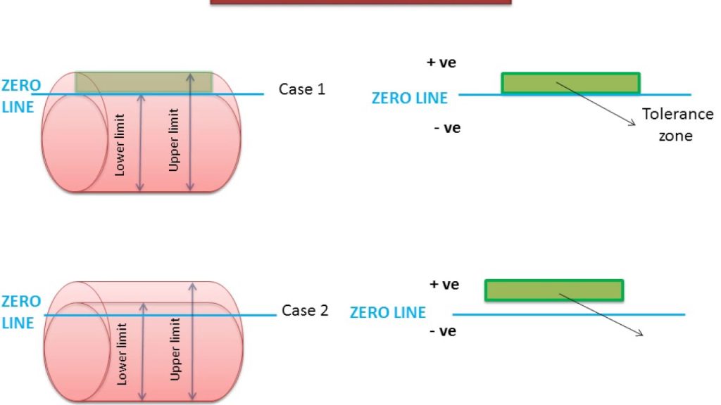
In hole basis system the hole is kept as the constant and the shaft upper and lower deviation values determine the type of fit. In hole basis system the Lower deviation of the hole will be Zero.
Example: Nominal Size of Hole 36mm
Hole = 36.000/36.015
Where
(Clearance Fit ) Shaft = 35.980/35.990 (Maximum Clearance = 0.035; Minimum Clearance = 0.010)
(Transition Fit) Shaft = 35.990/36.010 (Maximum Clearance = 0.030; Maximum Interference = 0.010)
(Interference Fit ) Shaft = 36.010/36.020 (Maximum interference = 0.020; Minimum Interference = 0.005)
(To calculate these values, Formulas are available here)
Shaft Basis system
In Shaft basis system the shaft is kept as the constant and hole upper and lower deviation values determine the type of fit. In shaft basis system the upper deviation of the shaft will be Zero.
Example: Nominal Size of shaft 25mm
Shaft = 24.985/25.000
Where
(Clearance Fit ) Hole = 25.010/25.020 (Maximum Clearance = 0.035; Minimum Clearance = 0.010)
(Transition Fit) Hole = 24.990/25.010 (Maximum Clearance = 0.025; Maximum Interference = 0.010)
(Interference Fit ) Hole = 24.980/24.990 (Maximum interference = 0.020; Minimum Interference = 0.005)
(To calculate these values, Formulas are available here)
Conclusion
Out of these two bases of limits systems, hole basis system is prefered over shaft basis system due to from manufacturing perspective it is easy to adjust the shaft dimension by using grinding or turning operation whereas holes are produced with drilling operations and it becomes complicated to do any further turning or grinding operations in holes.


