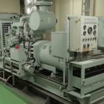
The most important routine maintenance for electrical machinery involves checking of insulation resistance, which is done by n instrument called “Megger ” or “ohmmeter ”.
Insulation Resistance
Insulation resistance (I.R) is a critical p m t s it’s directly l t d to personal safety, safety of machinery and power reliability. The I.R value of an electric device changes with aging, mechanical and electrical stresses, temperature, contamination, atmosphere, humidity etc. It is therefore important for seafarers to check this parameter for avoiding fatal accidents due to electrical shock.
Megger or Ohmmeter:
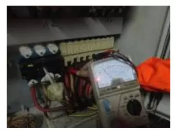
Megger is a portable instrument used to measure insulation resistance of electrical machinery or system. It is battery operated or mechanically operated (hand crank dc generator) and gives direct reading in ohms. Megger is used to measure voltage ratings in the range of 100V to 5000V.
Construction:
A Megger consists of following parts:
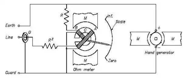
1) Control and Deflecting coils: They are normally mounted at right angle to each other and are connected parallel to the generator. The polarities are such that the torque produced by them is in the opposite direction.
2) Permanent Magnet: Permanent magnet with north and south poles are used for construction to produce magnetic effect for deflection of pointer.
3) Pointer and scale: A pointer is attached to the coils with its end floating on a scale ranging from “z o” to “infinity”. Th unit for this is “ohms”.
4) D.C generator or battery connection: Hand operated D.C generator supplies testing voltage for manually operated Megger. In automatic type Megger, testing voltage is supplied by battery and electronic voltage charger
5) Pressure coil and current coil: They are provided for preventing damage to the instrument in case of low external source resistance.
Working
· The voltage for testing is supplied by a hand generator incorporated in the instrument or by battery or electronic voltage charger. It is usually 250V or 500V and smaller in size
· A test volt of 500V D.C is suitable for testing ship’s equipment operating at 440V A.C. Test voltage of 1000V to 5000V is used for high voltage system onboard
· The current carrying coil (deflecting coil) is connected in series and carries the current taken by the circuit under test. The pressure coil (control coil) is connected across the circuit
· Current limiting resistor – CCR and PCR are connected in series with pressure and current coil to prevent damage in case of low resistance in external sources
· In hand generator, the armature is moving in the field of permanent magnet or vice versa, to generate a test voltage by electromagnetic induction effect
· With an increase of potential voltage across the external circuit, the deflection of the pointer increases and with an increase of current, the deflection of pointer decreases. Thus, the resultant torque on the movement is directly proportional to the potential difference and inversely proportional to the resistance
· When the external circuit is open, torque due to voltage coil will be maximum and the pointer will read “infinity”. When there is short circuit, the point will read “0”