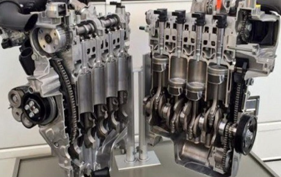
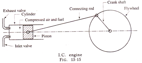
Fig. 13-15 shows the mechanical elements of the reciprocating I.C. engine. The piston which reciprocates in the cylinder is made a very close fit in the cylinder. In order to prevent the leakage of gas from one side of the piston to other side of it, piston rings are inserted in the circumferential grooves of the piston.
The cylinder is bored in the cylinder block may be bolted to the top of the crank case. The top of the cylinder is sealed down by bolting on to it the cylinder head. Generally gasket made of copper sheets and asbestos is inserted between the cylinder and cylinder head. The combustion space is provided in the top of cylinder head.
As the combustion takes place in the cylinder of an engine, it gets very hot. In order to preserve the engine materials and lubrication, the engine should be cooled. In fig. 13-16, the passages of cooling medium are shown cast in the walls of the cylinder block round the cylinder and also cast in the cylinder head round the combustion space.
The reciprocating motion of the piston is converted into the rotary motion of the crankshaft by means of connecting rod and crank. The connecting rod connects the piston and the crank, which is mounted on the crankshaft. The pin which connects the piston and the connecting rod is known as the gudgeon pin or piston pin.
The end of the connecting rod, which fits over the gudgeon pin, is called the small end of the connecting rod, while the other end which fits over the crank pin is called the big end of the connecting rod. Fig. 13-15 shows the sketch of I.C. engine.
The bottom of the engine is closed by means of a sump. This sump often contains the oil, which is pumped round the engine for lubrication.
A mechanical cycle for an internal combustion engine can be completed in one revolution (two stroke cycle) of the crankshaft or in two revolutions (four stroke cycle) of the crankshaft.
In an engine running on four stroke cycle principle, there are mechanically operated valves which control admission and exhaust to and from the engine cylinder. The opening and closing of the valves is controlled by means of cams which are fixed to the camshaft.
The camshaft is operated by means of a gear drive or chain drive from the crankshaft. The camshaft runs at half the speed of the crankshaft. The valves, which are known as poppet valves, are held down in closed position by means of valve springs.
In case of engine, working on two stroke cycle, the control of admission and exhaust is by means of ports, which are cut circumferentially in the cylinder walls. These ports are opened and closed by means of the moving piston. All these series of events form a complete cycle of events and these events take place in the same order in any cycle.
If all the events are completed in four strokes of the piston, then the engine is said to be working on Four Stroke Cycle principle. If on the other hand, these events are completed in two strokes of the piston then the engine is said to be working on Two Stroke Cycle principle. Fig. 13-6 shows the sketch of two stroke engine.

Comments are closed