Operating principles
Combustion is the process in which fuel heated beyond its flash point ignites and gives off energy and the waste products as exhaust gasses (carbon dioxide, carbon monoxide and water). The three elements necessary for combustion (or fire) are: Oxygen + Heat + Fuel = Explosion or Fire
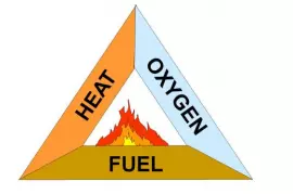
Internal combustion engines suck in air to access the oxygen and use hydrocarbon fuels including petrol, diesel and liquid propane gas.
The internal combustion process
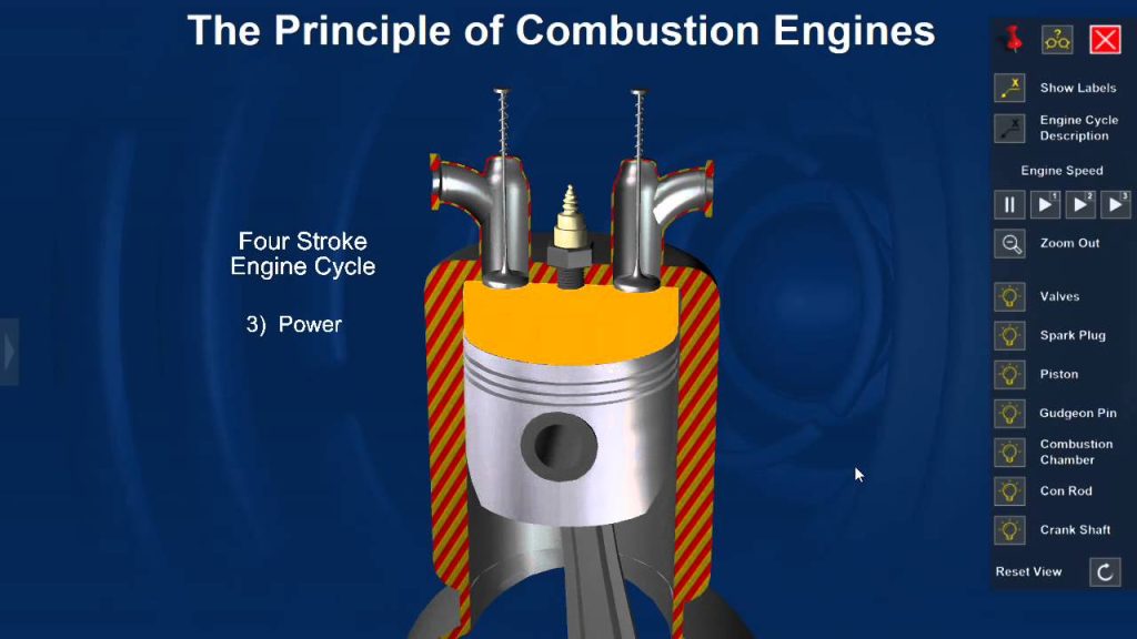
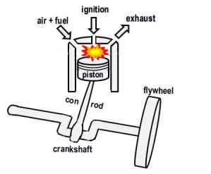
Internal combustion engines use successive explosions of atomised air and fuel mix to force a piston down a gas tight internal cylinder. The piston is connected through a big end bearing to a cranked shaft that is weighted by a flywheel to assist its rotary momentum. Thus with three primary moving parts (piston, connecting rod and crankshaft) the piston’s reciprocating motion drives the crankshaft’s rotary motion.
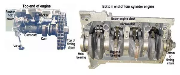
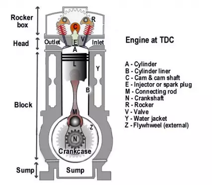
A sturdy metal casting of an engine block holds the internal parts and the many ancillary components required for smooth and continuous operation. These include:
The lubrication sump (oil reserve), a cylinder head with gas outlets and inlets, and in the drawing shown below, an overhead camshaft driven timing gear within a rocker box. For it to work at all timing is everything. The fuel (diesel, petrol or gas) and air (oxygen) charge must be inserted, the exhaust removed and a compression seal reinstated at the precise instant for the explosive ignition. The heat and noise from multiple explosions as well as wear on metal surfaces must be minimised.
To ensure a gas tight compression seal, the cylinder liners in the engine block are bored to very tight tolerances and the barrel of the piston is grooved to accept close fitting sprung metal rings – that makes for a tight sliding fit against the cylinder walls. In order to insert the fuel/air mix and exhaust the products of the combustion, sealable inlet and outlet passageways must be provided. Typically these passageways take the form of either ports (holes in the cylinder wall that are covered and uncovered by the passing of the piston) or by valves (steel stoppers that plug and unplug holes in the cylinder head at the correct timing intervals).
Basic features
The simplest engines often use ports and more the complex use valves, though hybrids like that shown below use both. The piston is connected to the big end bearing of the crankshaft by means of a connecting rod. The piston is forced down the cylinder by the expansion of combustion gases to turn the crankshaft. With the piston as low as it will go in the cylinder, it is said to be at bottom dead centre (bdc). The momentum of the flywheel weighted crankshaft rotating on its main bearings forces the piston back to the top of the cylinder, ready for the next explosion. When it is as high as it will go in the cylinder, it is at top dead centre (tdc).
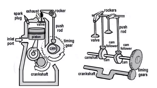
The distance the piston moves from tdc to bdc is called the stroke of the engine. The turning crankshaft drives the camshaft by means of timing gears (or by sprockets and a chain). In the drawing shown below, the side camshaft is driven by crankshaft gears. Oval cams on the camshaft open the inlet and exhaust valves at the correct time by means of push-rods actuating rockers. An inlet port (or alternately a valve) allows air or fuel/air mixture to be drawn into a cylinder ready for combustion, while an exhaust valve lets exhaust gas out of a cylinder.
The arrangement of ports or camshafts and valves differs depending on engine design. The drawing above shows a two stroke engine with its piston nearing tdc, its exhaust valve closed and inlet port covered, so compressing the fuel/air charge immediately prior to ignition. At the end of the power stroke the cam will open the exhaust valve to flush the cylinder ready for re-charge and re-ignition.