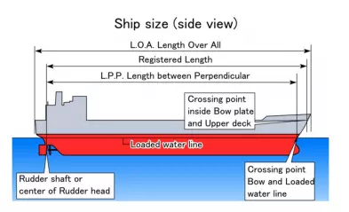
Length between perpendiculars, often abbreviated as p/p, p.p., pp, LPP, LBP or Length BPP is a term describing the length of a ship. LBP refers to the length of a vessel along the waterline from the forward surface of the stem, or main bow perpendicular member, to the after surface of the sternpost, or main stern perpendicular member. When there is no sternpost, the centreline axis of the rudder stock is used as the aft end of the length between perpendiculars.
Measuring to the stern post or rudder stock was believed to give a reasonable idea of the ship’s carrying capacity, as it excluded the small, often unusable volume contained in her overhanging ends. On some types of vessels this is, for all practical purposes, a waterline measurement. In a ship with raked stems, naturally that length changes as the draught of the ship changes, therefore it is measured from a defined loaded condition.
The significance lies in the fact that this length gives the length of the waterline of the vessel, in loaded condition, a very crucial parameter.
Annex 1 discharge criteria outside special area and inside special area for marine vessels
Inside special areas or outside special areas within 50 nm
ANY DISCHARGE IS PROHIBITED with the exception of clean or segregated ballast
Outside Special areas:
ANY DISCHARGE IS PROHIBITED, with the exception of clean or segregated ballast, or except when:
1. the tanker is proceeding en route, and
2. the instantaneous rate of discharge of oil does not exceed 30 litres/nm, and
3. the total quantity of oil discharged into the sea – does not exceed – for tankers delivered on or before 31 December 1979 – 1/15,000 of the total quantity of the particular cargo of which the residue formed a part – and – for tankers delivered after 31 December 1979 – 1/30,000 of the total quantity of the particular cargo of which the residue formed a part, and
4. the tanker has in operation an oil discharge monitoring and control system and a slop tank arrangement as required by regulations 29 and 31, respectively
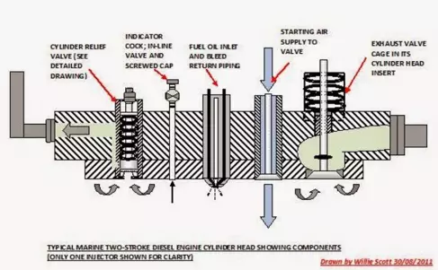
Cylinder Head – Cylinder head mountings, Function and Combustion chamber shape.
Cylinder head or cylinder cover houses various fixtures called cylinder head mountings. They are positioned and designed very carefully, as they are subjected to very high combustion pressures, and temperatures. Cylinder head mountings and functions are explained below in a brief sense.
Functions of cylinder head:
1. Forms a part of the combustion space- Cylinder head covers the top part of liner thus providing a space for combustion to take place. The shape of the cylinder head will greatly influence the combustion space shape, and thus characterstics and peak pressures developed in the engine. The efficiency of swirl and injection also depends on the Shape of this space.the three main Combustion chamber designs are Hemispherical pent roof, Bath tub and Wedge.
2. Cylinder head mountings- It houses various running parts like Exhaust/inlet valves, Fuel injectors, Relief valve, Air starting valve, Rocker arm, indicator cock, cooling water and fuel connections etc.
How to test emergency generator?? how would you take it on load??
For emergency standby generators (required by life-safety code), critical loads supported by the generator system typically include emergency lighting, fire alarm systems, fire pumps, and elevators. Life-safety generators are also sometimes used to additionally support optional loads, such as data centers; however, in this case the life-safety loads take precedence over the optional loads.
1. Fuel tank fuel supply levels piping, hoses and connectors; operating fuel pressure; and for any obstructions to tank vents and overflow piping.
2. Oil (check for proper oil level and oil operating pressure; lube oil heater) • Engine oil level can be checked with the unit stopped or running on many engines; otherwise, it should be checked with the unit stopped
3. Cooling system (check coolant level, water pump(s), jacket water heater, belts, hoses, fan)
4. Exhaust system (check drain condensate trap and for possible leakage)
5. Battery system [look for possible corrosion; check specific gravity, electrolyte level (a level between 1250 and 1275 is acceptable) and battery charger
6. Electrical (conduct a general inspection of wiring and connections; check circuit
breakers/fuses)
7. Prime Mover/Generator (Check for debris, foreign objects, loose or broken fittings; check guards and components; look for any unusual condition of vibration, leakage, noise, temperature or deterioration
NOTE: This is not an all-inclusive list. The equipment manufacturer may have additional maintenance requirements that will likely include monthly, quarterly, semiannual and annual inspections and checks.
Monthly testing
1. Emergency generators can be exercised monthly with the available load and exercised annually with supplemental loads at 25 percent of nameplate rating for 30 minutes, followed by 50 percent of nameplate rating for 30 minutes, followed by 75 percent of nameplate rating for 60 minutes, for a total of 2 continuous hours.
2. Load tests must include complete cold starts