The common rail system of fuel injection was used in marine diesel engines during the early and mid-19th century. These systems where well known in a particular type of engine famously called the “Doxford” engines or opposed piston engines. These engines are hard to find these days as they have been replaced by more efficient engines.
The common rail system of fuel injection is a simple and efficient system. The recent trend in the automobile industry is the usage of common rail direct fuel injection systems in some modern vehicles. Some of the engines in the automobile sector introduce this common rail system of injection not only in diesel engines, but also in petrol/gasoline engines. Lets discuss the operation of a marine diesel engine with a common rail fuel injection system.
Components and Operation of a Common Rail Injection System
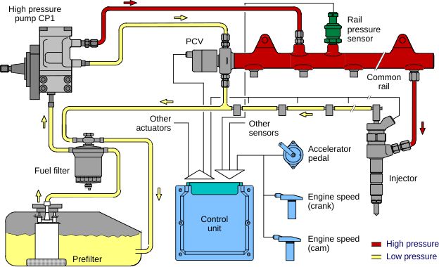
The common rail system has one or more common high pressure, multiple plunger, fuel pump/pumps. The fuel is discharged into a manifold preferably called a “rail” which is maintained at a very high pressure. From this common rail, fuel is supplied to all the fuel injectors in the various cylinder units. Between the rail and the injector or injectors for a particular cylinder is a “timing valve” which determines the timing and extent of fuel delivery. Spill valves are connected to the manifold or rail to release excess pressure and accumulator bottles are included to dampen out pump pressure pulses. The injectors in a common rail system are often referred to as fuel valves.

The timing valve in the common rail system is operated by a cam and a lever as shown in the figure below. When the timing valve is lifted by the cam, the lever also is lifted, thus ensuring that the valve in the timing valve block allows the high pressure fuel oil to reach the fuel injectors. Also, the timing valve operating lever is fixed to a sliding rod. This sliding rod is in turn fixed with the manoeuvring lever, which in turn governs the amount (quantity) of the fuel to be injected into each cylinder unit, meeting the load demands on the engine.

System Layout & Operation
As mentioned earlier, the system has a two or more common fuel pumps, which are driven by the main engine itself. They deliver high pressure fuel oil into one common line, thus called a “common rail” fuel injection system. This high pressure oil in the common rail tends to experience a pressure surge (shock), when the engine load changes suddenly or continuously over a period of time. To dampen these pressure surges, an accumulator bottle is provided on the high pressure line (common rail). It is specially marked in dark blue in the diagram below.

Also the volume capacity of the high pressure common rail is sufficient to suit sudden load changes. When compared with the individual pump engines, these common rail engines do not require a great deal of concentration at the drive shaft. As the fuel pumps supply fuel oil at a high pressure, it is stored against an accumulator pressure of around 400 to 550 atmospheres. This pressure is sufficiently maintained by the compressed air operated “spill valve.” If the pressure in the common rail increases suddenly, the spill valve will open up and drain the fuel oil to the service tank or the fuel oil drain tank as per the design. Then the timing valve controls the timing of start/stop of fuel injection.
For the initial start-up of the system, the fuel priming pump is provided, which can build up a pressure of about 140 atmospheres. This priming pump is usually pneumatically driven.
Many engines manufactured by seasoned marine engine manufacturers such as Sulzer and MAN have CRDI system. Read this article to know more about the SULZER RT FLEX & MAN B&W ME intelligent engines here
The Timing Valve: Operation
We all are aware of the fuel pump which we have witnessed in present days. These, which are often called “jerk type” pumps, can pump the fuel to the injectors, the start and termination of fuel injection as well as meter the correct amount of fuel to the fuel injectors, with respect to the engine load. But with the “common rail” system of fuel injection, with emphasis on the “Doxford” engines, the fuel pump, which is usually a reciprocating pump driven by the main engine, pumps fuel oil at a very high pressure into the common rail, but does not decide the start and stop of fuel injection. This is done by the “timing valves”, which are located in front of each unit. The timing valve controls the start/termination of fuel injection into the particular unit.
Referring to the figure beside, the timing valve and its cam are seen with the “common rail” high pressure line, on the discharge side of the reciprocating fuel pump. The reciprocating fuel pump is usually driven by the main engine itself and supplies fuel oil at a very high pressure to the common rail, which has a non-return valve and spill arrangement.
There is a separate accumulator bottle provided on the high pressure common rail line in order to avoid the pressure fluctuations or shock due to the change in load on the main engine. Then the high pressure fuel oil awaits for the opening of the timing valve (arrangement includes cam, lever, and valve block). When the cam peak lifts the lever up, the lever in turn opens the valve on the valve block, thus allowing the high pressure oil to reach the fuel injectors mounted on the cylinders of each unit. As the engine crankshaft rotates, thus making the cam to rotate causing the peak to move, the lever returns back from its lifted position, thus allowing the valve on the valve block to close,stopping further fuel oil flow to the fuel injectors.
The duration of the opening of the valve in the valve block determines the fuel injection period. The duration of the opening of the valve in the valve block can be altered by adjusting the fulcrum point on the valve lifting lever “L.” At no delivery, the fulcrum remains at its lowest position. During this stage, the cam peak just oscillates the lever, but the valve is not opened in the valve block, thus no fuel is being injected.
The fuel pumps are capable of metering the correct amount of fuel to each unit. Based on the engine load, the governor controls the fuel rack of the fuel pump as seen in the adjacent figure. This regulated quantity of fuel is pumped by the fuel pump towards the timing valve. These fuel pumps have a helical slot in the plunger, the same as in conventional pumps. This ensures that the correct quantity of fuel is always injected with respective variation in engine load.

Modern Engines With Common Rail Fuel Injection Systems
With the technology developing exponentially, recent marine propulsion and power generation engines have started coming back towards the common rail system of fuel injection. In the recent development of the camshaft-less MAN B&W ME intelligent series of engines and the SULZER FLEX engines, the individual jerk fuel pumps are replaced by a common single or multiple fuel pumps of reciprocating type which conveys high pressure oil to a common rail. So these good old common rail systems are back with these latest engines.It is to be noted that the SULZER RT FLEX engines uses common rail system of fuel injection but the MAN B&W ME intelligent engines does not.


Comments are closed