Bending stress is one of the major reasons for failure or cracks in the ship’s Main engine support girders of the bed plate, installed just below the main bearing. To minimize this problem, SULZER uses Jack bolts instead of holding bolts for the main bearing.
What are Jack Bolts?
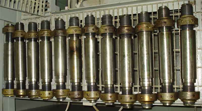
Jack bolts are hydraulically tightened long studs with incorporated hydraulic connection which holds the upper keep of the main bearing intact. They do not pass through the main bearing keep housing but do hold the keep by using hydraulic tension applied and maintained externally.

The Jack Bolts are at an angle of 15 ̊ with the vertical plane and tightened at hydraulic pressure of around 600 bars.
Advantage of Jack bolts
The jack bolts are mounted on the top of the upper keep, unlike conventional holding bolt which are placed at side of the keep as they are passed through the hole provided on the housing for their stud.
This allows the tie rod to be placed nearer to the crank shaft center line, which ultimately reduces the bending stresses on the cross girder of the engine.
Opening procedure for Jack Bolts
1. Remove the locking wire ‘11’.
2. Unscrew threaded plugs for oil input to cylinder ‘7’ and in their place screw in connectors 94933 firmly. Connect them to HP oil p/p 94931.
3. Tension jack bolts with about 620 bars and keep this pressure constant until both nuts ‘8’ have been unscrewed by about 1 to 2 turns. Release pressure to zero by opening release valve ‘V’. And remove the connector 94933.
4. Unscrew both nuts ‘8’ until the jack bolts can be removed. Close oil input holes again with threaded plugs to prevent entry of dirt.

Tools: Key to illustration:
1 special feeler gauge -94123 1. Thrust bolt 8. Nut
1 Depth gauge -94126 2. Column centre part 9. Milled face for spanner
1 HP oil -94931 3. Bearing cover 10. piston seal ring
3 Pressure Gauges 1000 bar -94932 4. Vent v/v 11. Locking wire
2 connectors -94933 5. Lock wire D- pressure space
HP hoses -94935 6. Set screw S- round bar
Open end spanner to item 9 7. Cylinder V- Release valve
Tensioning of Jack Bolts
1. Compare the three pressure gauges 94932 with a calibrated pressure gauge to correct pressure.
2. Clean the seating surface of the jack bolts on the main bearing keep.
3. Fit the thrust bolts turning their cylinder ‘7’ to such a position that the connectors with pressure gauge can be fitted, tighten nut ‘8’ with a round bar ‘S’ (without any extension).
4. Screw in both connectors and then connect them to HP hydraulic p/p.
5. Establish distance ‘a1’ and ‘a2’ with depth gauge 94126. The difference between them should not increase by 0.1mm.
6. Remove locking wire ‘5’ and slightly loosen vent valve ‘4’ while actuating the oil pump till all the air is removed from pressure space ‘D’. Then tighten vent v/v ‘4’ and lick it with locking wire ‘5’.
7. Now give a pressure of 600 bars and make sure all the 3 pressure gauges show same pressure. Hold this pressure.
8. Tighten both nuts ‘8’ with a round bar ‘S’ till fully seated on cylinder ‘7’(check seating with feeler gauge)
9. Release the pressure and check distance ‘a1’ and ‘a2’, difference should not be more than 0.1mm.
10. Finally lock the jack bolt with a locking wire ‘11’.


Comments are closed