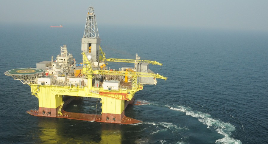
They are floating installations which rest on four or six pillar-like legs called columns with a equal weight distribution on each. These columns or legs are in turn attached to large basements called pontoons floating on the water surface. These pontoons may be ballasted or de-ballasted accordingly on and off operations. Often these pontoons delve deeper under the water surface and maintain the buoyancy and position of the floating system. There is always a greater draft. Thereafter the operational deck is kept well aloof from the wave disturbance or the rough seas. However due to small waterplane area the structure is sensitive to load variations and must be trimmed accordingly. They by the virtue of their equivalent weight distribution and a high draft, it has a greater stability than normal ships. The number of legs, pontoon design , the situation of the risers and drill equipment are decided at pre-design stage. They are generally instrumental in Ultra-deep waters where the fixed structures pose a problem. Their position is maintained generally by a catenary mooring system or sometimes in modern structures by Dynamic :Positioning System. These structures are gigantic and may be towed from one location to another by the virtue of a kind of ships called Heavy Lift ships.
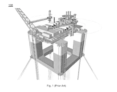
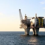
Fig. 8: Semi-submersible Offshore Platform
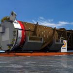
| Fig. 9: Heavy Lift Ship |
SPARS
These have a large diameter cylindrical deck supporting the main deck .They are generally developed as oil platforms for deeper waters as an alternative to the conventional systems. Most of the drilling and oil extraction equipment are situated within them. The inside part of the cylindrical truss is filled with some material denser than the sea-water to lower down the centre of gravity and hence maintain the vertical stability of the structure. The deep draft design of spars makes them less affected by wind, wave and currents and allows for both dry tree and subsea production. The cylindrical structure is surrounded by helical strakes to avoid vortex-induced motion.
The first prototype of the SPAR Platform was Neptune laid off the US coast in 1997.
There are basically three types of spars, namely, truss spar, classic spar and cell spar.
It is generally equipped with taut catenary mooring and the heave natural period is generally below 30 seconds. Generally , the spar is employed for depths up to 2300 m. The number of risers is restricted generally due to the limited space of the core cylinder. These are highly stable and hence are negligible unaffected even on adverse sea conditions or sharp environmental vagaries.
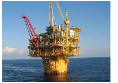
Fig. 10: A typical deep sea SPAR Platform (Courtesy:www.maritimeconnector.com)
FPSOs
FPSOs stand for Floating, Production, Storage and Offloading Systems. It is a specialized vessel for the purpose of offloading, processing, storage, distribution of oil and other hydrocarbon resources. One important point to wonder is that these installations does not have anything to do with the extraction purposes and can be merely reckoned as a carrier with specialization. These vessels eradicate the need of long pipelines for transfer of oil and petroleum to the shore. FPSOs are preferred in frontier offshore regions as they are easy to install, and do not require a local pipeline infrastructure to export oil. FPSOs can be a conversion of an oil tanker or can be a vessel built specially for the application. A vessel used only to store oil (without processing it) is referred to as a floating storage and offloading vessel (FSO). These can operate extensively in remote and deep waters and also in marginal wells where fixed platform or piping is technically or economically not feasible.
In majority of the cases the vessel may be buoyed to a vicinal drilling platform. Also the oil or other petroleum products maybe transported to the mainland by pipelines or by a conventional mooring system. The vessel may be fixed in a particular position by mooring lines or by a dynamic positioning system (DPS).
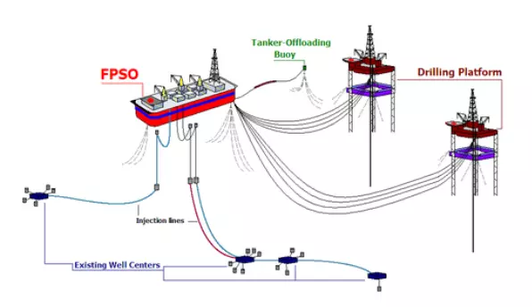
Fig.11: The ongoing operations to an FPSO and the production process
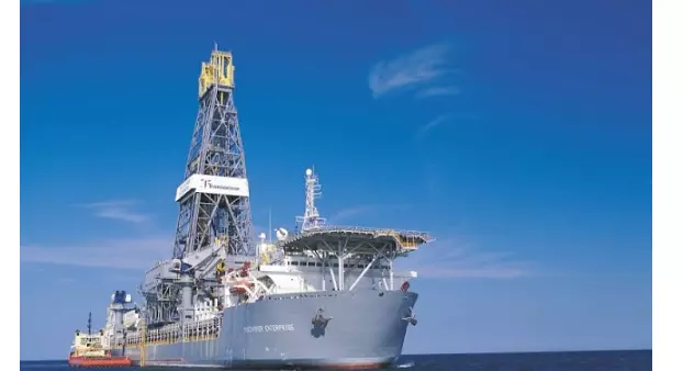
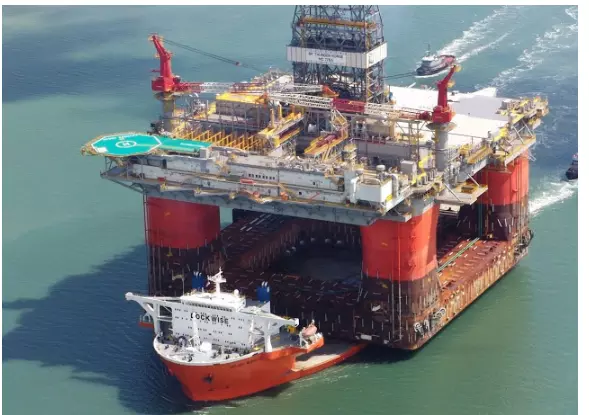
| Fig.12: Floating production storage and offloading unit |
These ships have an integral storage capability inside their voluminous hull and have a calculated freeboard and draught. They are operational in adverse weather and have a high maintenance cost.
Comments are closed