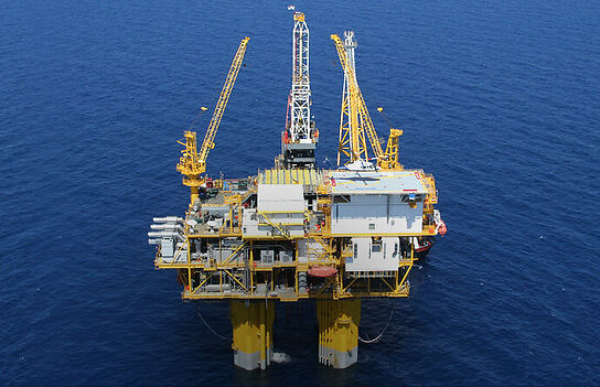
The majority of offshore fields have been developed with conventional fixed steel platforms. One common feature of fixed steel structures is that it is essentially “fixed” (i.e., it acts as a cantilever fixed at the seabed). This forces the natural period to be less than that of the damaging significant wave energy, which lies in the 8- to 20-second band. As the water depth increases, these structures begin to become more flexible, and the natural period increases and approaches that of the waves. The consequence of this is the structure becomes dynamically responsive, and fatigue becomes a paramount consideration. Additional steelwork is required to stiffen the structure.
Compliant towers
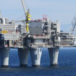
Compliant towers are three-dimensional (3D) steel truss arrangements, which are slender and have a seabed footprint substantially less than an equivalent steel-jacket structure; see Fig. 1 and Fig. 2.
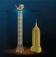
Fig. 1—The Baldpate Compliant Tower is one of the tallest free-standing structures in the world – Empire State Building (right) for comparison
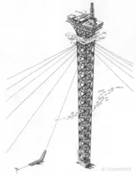
Fig. 2—Guyed tower concept
Guyed tower concept
The freestanding compliant tower concept (Fig. 1, adopted for the Petronius platform in the Gulf of Mexico) and the guyed tower concept (Fig. 2, adopted for the Lena platform in the Gulf of Mexico) are sized on the principle of “compliance” to wave attack. Vertical and lateral stability is assured through the use of either flotation devices (Fig. 1) and guys (Fig. 2). The dynamic response of a compliant tower is crucial, and dynamic analyses form part of the design process for this structure. Another design and engineering focus relates to the foundation pile design. As the structure deflects, significant tension-compression coupling forces are introduced in the piles. Locating the piles near the center of the tower, limiting the maximum tower deflections, and selecting piles of sufficient length to absorb the imposed loads can limit the resulting stresses in the piles. Compliant towers can be constructed using techniques that have evolved for steel-jacket structures. A two-piece construction and installation can be adopted, as was used for the Petronius platform installation.
Tension leg platforms (TLP)
Fig. 3 illustrates the TLP concept. The topsides equipment and facilities are not dissimilar to those usually deployed for fixed steel structures. The platform comprises a deck structure and a buoyant hull that is composed of a series of vertical cylindrical columns, horizontal submerged pontoons, and, in some instances, tubular member bracing. The platform is tethered to the seabed by a number of tendons that are kept in tension at all times by the excess buoyancy in the hull. These tendons suppress the heave motions, and the tension ensures that the platform remains virtually horizontal even at lateral excursions of up to 10% of the water depth. Lateral excursions are controlled because the tendons develop a restoring force as lateral movements take place.
Fig. 3—TLP concept
Foundation system
The tendons are secured in a foundation template piled into the seabed. The foundation system is subjected to cyclic loads superimposed on a high-tension load. Therefore, care is required in the analysis and design of the foundation system. Nevertheless, while the foundation system may appear elaborate, the advantages are considerable. The restriction on vertical movement permits the use of fixed-steel-platform-type wellhead equipment and rigid steel riser conductor assemblies.
Production risers
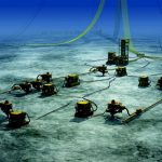
The production risers may suffer from vortex-induced vibrations (VIV) caused by the current, especially in high-current regions such as the Gulf of Mexico and the West of Shetlands. Riser spacing design is of prime importance; As illustrated in Fig. 4, if the design principle were for no contact between the risers, a cost penalty in ultra-deep water would be expected; If contact between risers is the accepted design principle, it is then important to predict their dynamic behavior, evaluate the impact energy during contact, and define acceptance criteria.
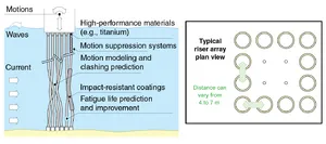
Fig. 4—Riser spacing and contact considerations (courtesy of BP).
Construction techniques
The TLP is not dissimilar to a semisubmersible, and construction techniques developed for semisubmersibles can be deployed for TLPs. However, the buoyancy requirements for a TLP may be two to five times that of a semisubmersible, and, therefore, construction facilities used for semisubmersibles may be too small for TLP fabrication. A TLP deck may be fabricated separately from the hull and mated in a manner similar to that adopted for concrete gravity base platforms. The benefit is the reduced construction time. Alternatively, a single-piece construction can be adopted for the deck and hull with equipment and facilities placed on the completed platform. In this instance, intermediate structural bracing can be accommodated because barge clearance is not required.
Placement
A number of options exist for the placement of the template(s) and piling. A single template for the foundation and well system can be adopted, or separate templates can be specified. Tendons may be attached to the template or directly to the piles. The advantages and disadvantages for each option are considered at the design stage from both engineering (redundancy, robustness, etc.) and economic standpoints.
Deep draft floaters
A deep-draft floater is a floating system that is provided with a deep-draft hull designed to minimize heave motions. An example of a deep-draft facility designed by CSO Aker is shown in Fig. 5. This particular concept is more commonly known as a truss spar. Other forms of deep-draft floaters include deep-draft semisubmersibles and hull arrangements other than the arrangement shown in Fig. 5.
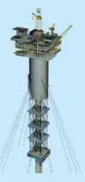
Fig. 5—A typical truss spar (courtesy of BP).
The concept shown in Fig. 5 has successfully been deployed for the Horn Mountain field and has been chosen for the Holstein field, both of which are in the Gulf of Mexico. The upper section of the hull is a conventional cylindrical shell and provides the required buoyancy for the platform. A center well within the cylinder protects the production risers and their tensioning system. The lower section is a braced truss system with heave plates to achieve the desired heave motion characteristics. In common with all spars, the vertical risers support the dry trees at the topsides, thereby providing continuous access to the wells for re-entry. A keel section at the base of the truss is specified for buoyancy during towing and contains fixed ballast.
Mooring
Mooring is achieved using a taut system of mooring lines composed of chain and wire or polyester. The lines are moored to the seabed using a vertically loaded anchor. The mooring system is designed to accommodate a platform offset of several hundred feet for drilling or workover purposes.
Typical fixed platform design practices are applicable for the topside configurations with the exception that, because the spar is a floating system, lateral accelerations are higher. A payload of up to 50,000 tons can be accommodated, including drilling or workover rig and full production equipment.
Deep draft floaters
Deep-draft floaters, either of the cylindrical arrangement (such as spars) or of the semisubmersible configuration, are likely to find increasing favor in deepwater applications in the future. The systems can be designed for storage capability as well. The choice between these two and other floating production systems depends on the fundamental decision on the need for dry-trees or wet-trees.
Wet verses dry trees
All the concepts discussed and described allow for the wellheads and Christmas tree valve systems to be above the waterline (i.e., in the dry). The size and type of reservoir and the anticipated extent and cost of well intervention often dictate the selection of dry vs. wet trees. The type of field development concept utilized, in particular the choice between wet and dry trees, significantly affects all aspects of the development, from the appraisal strategy and development concept to reservoir and field management.
Dry trees
Dry trees allow direct and continuous access to the wells for maintenance and re-entry. A number of offshore platform concepts exist that meet the dry tree requirement. These include conventional jackets, spars, and TLPs.
Wet trees
Wet trees, so-called because the wellheads and Christmas trees are placed on the seabed. These are sometimes referred to as subsea completions. For wet trees, possible development concepts include all of these plus ship-shaped floating production systems and semisubmersible production systems.
Floating production systems (FPS)
A floating production system is effectively a floating rig. It contains all the equipment associated with a fixed platform and is used in conjunction with subsea wellheads to exploit moderate to deepwater fields, particularly where the installation of a fixed platform is neither practical nor cost-effective. For all floating systems, a range of stability criteria is followed to ensure system stability in calm waters with sufficient safety margins to allow for the dynamic conditions of stormy seas. The primary considerations for stability revolve around the location of the center of gravity and the relative location of the center of buoyancy; see Fig. 6. As the floating structure heels, it gives rise to a restoring moment, which stabilizes the system.
· 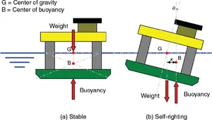
Fig. 6—Stability of floating systems (courtesy of MSL Engineering).
Conventional FPS
A conventional FPS typically uses either a semisubmersible to accommodate the equipment and utilities or a ship-shaped monohull, the latter often built from converted oil tankers. A spread of mooring lines is used for station keeping during production, and flexible flow lines are adopted, which permit wave-induced vessel motions to be absorbed.
Monohull FPS
The advantage of the monohull FPS is primarily that processed oil can be stored on board the vessel prior to export, making them in effect FPSO facilities.
Disadvantages
The main drawback for semisubmersibles is the lack of storage capacity to prevent shutdowns when offloading operations are disrupted.
As water depth increases, the length and, hence, weight of conventional wire and chain mooring systems increase. Floating structures must increase in size to provide the necessary buoyancy to carry the extra weight, which adds incremental cost to the development. Further, many of the conventional mooring systems are deployed in the catenary configuration, giving low stiffness, which allows considerable offsets and poor response. This is undesirable for operational reasons and often requires use of flexible riser systems to compensate for the movement.
To overcome the weight problems associated with wire/chain moorings, synthetic materials, such as polyester, are being evaluated and have been applied as a replacement for conventional steel ropes and chain mooring systems. They have less weight and, in the taut configuration, provide lower vessel movement and a reduced footprint on the seabed.
The interaction between risers and moorings is self-evident. One of the functions of the moorings is to guarantee the integrity of the risers, but moorings are subject to practical limits regarding their numbers and strength. Assessments for the risk of mooring failure should therefore reflect this unavoidable interaction between the adopted riser and mooring systems.
Deepwater riser
Deepwater riser systems have been acknowledged by the industry as representing critical technology for current planned and future field developments. Drilling and production risers can be of the top-tensioned arrangement. Load and fatigue limitations for these risers are a significant challenge. VIV and VIM can significantly reduce the fatigue life of both the riser and the wellhead. The matter of riser contact and clashing is covered in the TLP subsection above. It should be recognized that prediction of the dynamic response for an array of top-tensioned risers is nontrivial, given the hydrodynamic interaction.
Comments are closed