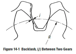
In order to obtain the amount of backlash desired, it is necessary to decrease tooth thickness. See Figure 14-1. This decrease must almost always be greater than the desired backlash because of the errors in manufacturing and assembling. Since the amount of the decrease in tooth thickness depends upon the accuracy of machining, the allowance for a specified backlash will vary according to the manufacturing conditions.
It is customary to make half of the allowance for backlash on the tooth thickness of each gear of a pair, although there are exceptions. For example, on pinions having very low numbers of teeth, it is desirable to provide all of the allowance on the mating gear so as not to weaken the pinion teeth.
In spur and helical gearing, backlash allowance is usually obtained by sinking the hob deeper into the blank than the theoretically standard depth. Further, it is true that any increase or decrease in center distance of two gears in any mesh will cause an increase or decrease in backlash. Thus, this is an alternate way of designing backlash into the system.
In the following, we give the fundamental equations for the determination of backlash in a single gear mesh. For the determination of backlash in gear trains, it is necessary to sum the backlash of each mated gear pair. However, to obtain the total backlash for a series of meshes, it is necessary to take into account the gear ratio of each mesh relative to a chosen reference shaft in the gear train. For details, see Reference 10 at the end of the technical section.
Definition Of Backlash
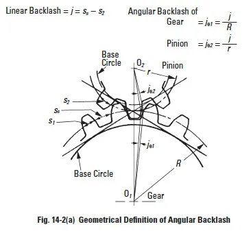
Figure 14-2a
Backlash is defined in Figure 14-2(a) as the excess thickness of tooth space over the thickness of the mating tooth. There are two basic ways in which backlash arises: tooth thickness is below the zero backlash value; and the operating center distance is greater than the zero backlash value.
If the tooth thickness of either or both mating gears is less than the zero backlash value, the amount of backlash introduced in the mesh is simply this numerical difference:
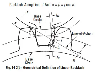
Figure 14-2b
where:
j = linear backlash measured along the pitch circle (Figure 14-2(b))
sstd = no backlash tooth thickness on the operating pitch circle, which is the standard tooth thickness for ideal gears
sact = actual tooth thickness
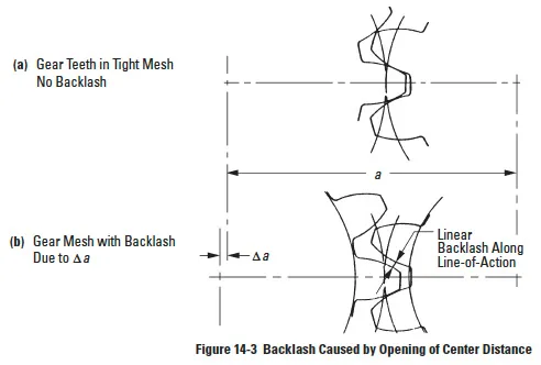
When the center distance is increased by a relatively small amount, Δa, a backlash space develops between mating teeth, as in Figure 14-3. The relationship between center distance increase and linear backlash jn along the line-of-action is:
This measure along the line-of-action is useful when inserting a feeler gage between teeth to measure backlash. The equivalent linear backlash measured along the pitch circle is given by:
where:
Δ a = change in center distance
α = pressure angle
Hence, an approximate relationship between center distance change and change in backlash is:

Although these are approximate relationships, they are adequate for most uses. Their derivation, limitations, and correction factors are detailed in Reference 10.
Note that backlash due to center distance opening is dependent upon the tangent function of the pressure angle. Thus, 20° gears have 41° more backlash than 14.5° gears, and this constitutes one of the few advantages of the lower pressure angle.
Equations (14-3) are a useful relationship, particularly for converting to angular backlash. Also, for fine pitch gears the use of feeler gages for measurement is impractical, whereas an indicator at the pitch line gives a direct measure. The two linear backlashes are related by: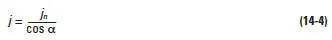
The angular backlash at the gear shaft is usually the critical factor in the gear application. As seen from Figure 14-2(a), this is related to the gear’s pitch radius as follows: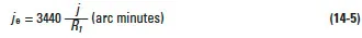
Obviously, angular backlash is inversely proportional to gear radius. Also, since the two meshing gears are usually of different pitch diameters, the linear backlash of the measure converts to different angular values for each gear. Thus, an angular backlash must be specified with reference to a particular shaft or gear center.
Details of backlash calculations and formulas for various gear types are given in the following sections.
Backlash Relationships
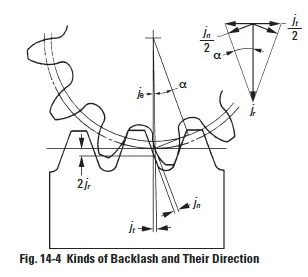
Figure 14-4
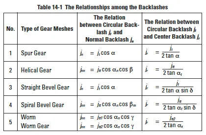
Table 14-1
Expanding upon the previous definition, there are several kinds of backlash: circular backlash jt, normal backlash jn, center backlash jr , and angular backlash Jθ (°), see Figure 14-4.
Table 14-1 reveals relationships among circular backlash jt, normal backlash jn and center backlash jr. In this definition, jr is equivalent to change in center distance, Δa, in Section 14.1.
Circular backlash jt has a relation with angular backlash jθ, as follows: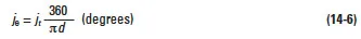
14.2.1 Backlash Of A Spur Gear Mesh
From Figure 14-4 we can derive backlash of spur mesh as: 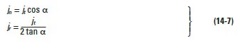
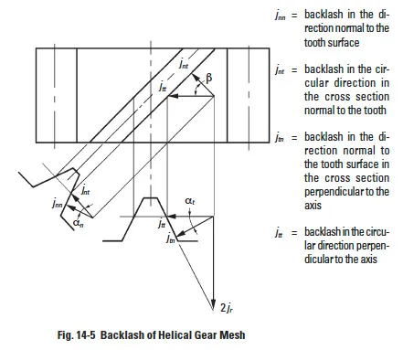
Backlash Of Helical Gear Mesh
The helical gear has two kinds of backlash when referring to the tooth space. There is a cross section in the normal direction of the tooth surface n, and a cross section in the radial direction perpendicular to the axis, t.
These backlashes have relations as follows:
In the plane normal to the tooth:
On the pitch surface: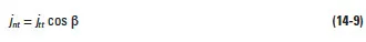
In the plane perpendicular to the axis: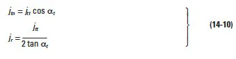
Figure 14-6 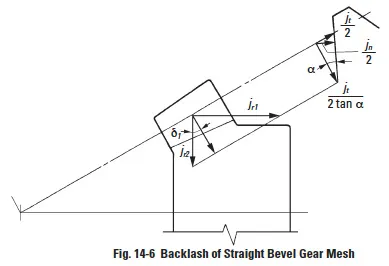
Backlash Of Straight Bevel Gear Mesh
Figure 14-6 expresses backlash for a straight bevel gear mesh.
In the cross section perpendicular to the tooth of a straight bevel gear, circular backlash at pitch line jt, normal backlash jn and radial backlash jr’ have the following relationships: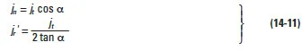
The radial backlash in the plane of axes can be broken down into the components in the direction of bevel pinion center axis, jr1, and in the direction of bevel gear center axis, jr2. 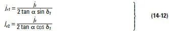
Backlash Of A Spiral Bevel Gear Mesh
Figure 14-7 delineates backlash for a spiral bevel gear mesh.
Figure 14-7 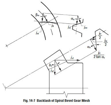
In the tooth space cross section normal to the tooth: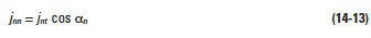
On the pitch surface:
In the plane perpendicular to the generatrix of the pitch cone: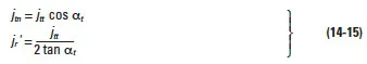
The radial backlash in the plane of axes can be broken down into the components in the direction of bevel pinion center axis, jr1, and in the direction of bevel gear center axis, jr2.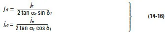
Figure 14-8 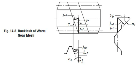
Backlash Of Worm Gear Mesh
Figure 14-8 expresses backlash for a worm gear mesh.
On the pitch surface of a worm: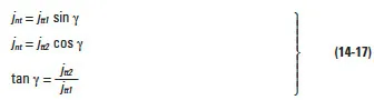
In the cross section of a worm perpendicular to its axis: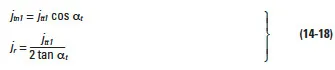
In the plane perpendicular to the axis of the worm gear: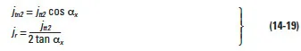
Tooth Thickness And Backlash
There are two ways to produce backlash. One is to enlarge the center distance. The other is to reduce the tooth thickness. The latter is much more popular than the former. We are going to discuss more about the way of reducing the tooth thickness. In SECTION 10, we have discussed the standard tooth thickness s. In the meshing of a pair of gears, if the tooth thickness of pinion and gear were reduced by Δs1 and Δs2, they would generate a backlash of Δs1 + Δs2 in the direction of the pitchcircle.
Let the magnitude of Δs1, Δs2 be 0.1. We know that α = 20°, then:
jt = Δs1 + Δs2 = 0.1 + 0.1 = 0.2 We can convert it into the backlash on normal direction:
jn = jt cos α = 0.2 cos 20° = 0.1879
Let the backlash on the center distance direction be jr, then: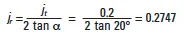
They express the relationship among several kinds of backlashes. In application, one should consult the JIS standard.
There are two JIS standards for backlash – one is JIS B 1703-76 for spur gears and helical gears, and the other is JIS B 1705-73 for bevel gears. All these standards regulate the standard backlashes in the direction of the pitch circle jt or jtt. These standards can be applied directly, but the backlash beyond the standards may also be used for special purposes. When writing tooth thicknesses on a drawing, it is necessary to specify, in addition, the tolerances on the thicknesses as well as the backlash. For example:
Backlash 0.100 … 0.200
Figure 14-9 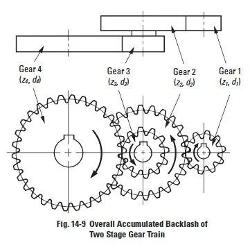
Gear Train And Backlash
The discussions so far involved a single pair of gears. Now, we are going to discuss two stage gear trains and their backlash. In a two stage gear train, as Figure 14-9 shows, j1 and j4 represent the backlashes of first stage gear train and second stage gear train respectively. If number one gear were fixed, then the accumulated backlash on number four gear jtT4 would be as follows:
This accumulated backlash can be converted into rotation in degrees:
The reverse case is to fix number four gear and to examine the accumulated backlash on number one gear jtT1.
This accumulated backlash can be converted into rotation in degrees:
Methods Of Controlling Backlash
In order to meet special needs, precision gears are used more frequently than ever before. Reducing backlash becomes an important issue. There are two methods of reducing or eliminating backlash – one a static, and the other a dynamic method.
The static method concerns means of assembling gears and then making proper adjustments to achieve the desired low backlash. The dynamic method introduces an external force which continually eliminates all backlash regardless of rotational position.
Static Method
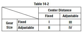
This involves adjustment of either the gear’s effective tooth thickness or the mesh center distance. These two independent adjustments can be used to produce four possible combinations as shown in Table 14-2.
Case I
By design, center distance and tooth thickness are such that they yield the proper amount of desired minimum backlash. Center distance and tooth thickness size are fixed at correct values and require precision manufacturing.
Case II
With gears mounted on fixed centers, adjustment is made to the effective tooth thickness by axial movement or other means. Three main methods are:
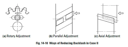
- Two identical gears are mounted so that one can be rotated relative to the other and fixed. See Figure 14-10a. In this way, the effective tooth thickness can be adjusted to yield the desired low backlash.
- A gear with a helix angle such as a helical gear is made in two half thicknesses. One is shifted axially such that each makes contact with the mating gear on the opposite sides of the tooth. See Figure 14-10b.
- The backlash of cone shaped gears, such as bevel and tapered tooth spur gears, can be adjusted with axial positioning. A duplex lead worm can be adjusted similarly. See Figure 14-10c.
Case III
Center distance adjustment of backlash can be accomplished in two ways:
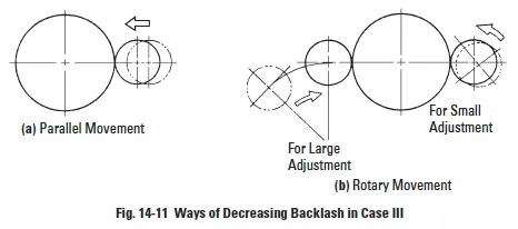
- Linear Movement – Figure 14-11a shows adjustment along the line-of-centers in a straight or parallel axes manner. After setting to the desired value of backlash, the centers are locked in place.
- Rotary Movement – Figure 14-11b shows an alternate way of achieving center distance adjustment by rotation of one of the gear centers by means of a swing arm on an eccentric bushing. Again, once the desired backlash setting is found, the positioning arm is locked.
Case IV
Adjustment of both center distance and tooth thickness is theoretically valid, but is not the usual practice. This would call for needless fabrication expense.
Dynamic Methods
Dynamic methods relate to the static techniques. However, they involve a forced adjustment of either the effective tooth thickness or the center distance.
- Backlash Removal by Forced Tooth Contact
This is derived from static Case II. Referring to Figure 14-10a, a forcing spring rotates the two gear halves apart. This results in an effective tooth thickness that continually fills the entire tooth space in all mesh positions. - Backlash Removal by Forced Center Distance Closing
This is derived from static Case III. A spring force is applied to close the center distance; in one case as a linear force along the line-of-centers, and in the other case as a torque applied to the swing arm.
In all of these dynamic methods, the applied external force should be known and properly specified. The theoretical relationship of the forces involved is as follows: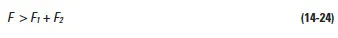
where:
F1 = Transmission Load on Tooth Surface
F2 = Friction Force on Tooth Surface
If F < F1 + F2, then it would be impossible to remove backlash. But if F is excessively greater than a proper level, the tooth surfaces would be needlessly loaded and could lead to premature wear and shortened life. Thus, in designing such gears, consideration must be given to not only the needed transmission load, but also the forces acting upon the tooth surfaces caused by the spring load. It is important to appreciate that the spring loading must be set to accommodate the largest expected transmission force, F1, and this maximum spring force is applied to the tooth surfaces continually and irrespective of the load being driven.
Figure 14-12 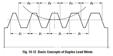
- Duplex Lead Worm
A duplex lead worm mesh is a special design in which backlash can be adjusted by shifting the worm axially. It is useful for worm drives in high precision turntables and hobbing machines. Figure 14-12 presents the basic concept of a duplex lead worm.
The lead or pitch, pL and pR, on the two sides of the worm thread are not identical. The example in Figure 14-12 shows the case when pR > pL. To produce such a worm requires a special dual lead hob.
The intent of Figure 14-12 is to indicate that the worm tooth thickness is progressively bigger towards the right end. Thus, it is convenient to adjust backlash by simply moving the duplex worm in the axial direction.
SECTION 15: GEAR ACCURACY
Gears are one of the basic elements used to transmit power and position. As designers, we desire them to meet various demands:
- Minimum size.
- Maximum power capability.
- Minimum noise (silent operation).
- Accurate rotation/position.
To meet various levels of these demands requires appropriate degrees of gear accuracy. This involves several gear features.
Accuracy Of Spur And Helical Gears
This discussion of spur and helical gear accuracy is based upon JIS B 1702 standard. This specification describes 9 grades of gear accuracy – grouped from 0 through 8 – and four types of pitch errors:
· Single pitch error.
· Pitch variation error.
· Accumulated pitch error.
· Normal pitch error.
Single pitch error, pitch variation and accumulated pitch errors are closely related with each other.
Pitch Errors of Gear Teeth
- Single Pitch Error (fpt)
The deviation between actual measured pitch value between any adjacent tooth surface and theoretical circular pitch. - Pitch Variation Error (fpu)
Actual pitch variation between any two adjacent teeth. In the ideal case, the pitch variation error will be zero. - Accumulated Pitch Error (Fp)
Difference between theoretical summation over any number of teeth interval, and summation of actual pitch measurement over the same interval. - Normal Pitch Error (fpb)
It is the difference between theoretical normal pitch and its actual measured value.
The major element to influence the pitch errors is the runout of gear flank groove.
Table 15-1 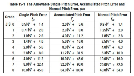
Table 15-1 contains the ranges of allowable pitch errors of spur gears and helical gears for each precision grade, as specified in JIS B 1702-1976.
In the above table, W and W’ are the tolerance units defined as: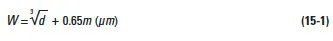

Table 15-2 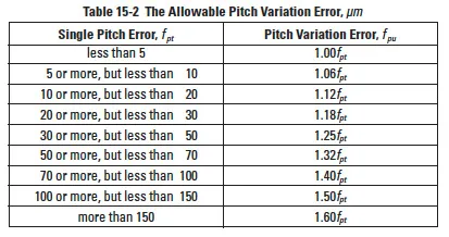
The value of allowable pitch variation error is k times the single pitch error. Table 15-2 expresses the formula of the allowable pitch variation error.
Figure 15-1 is an example of pitch errors derived from data measurements made with a dial indicator on a 15 tooth gear. Pitch differences were measured between adjacent teeth and are plotted in the figure. From that plot, single pitch, pitch variation and accumulated pitch errors are extracted and plotted.
Figure 15-1 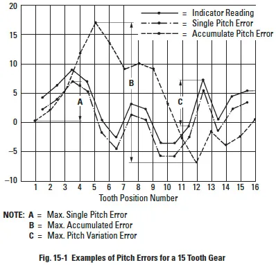
Tooth Profile Error, ff
Tooth profile error is the summation of deviation between actual tooth profile and correct involute curve which passes through the pitch point measured perpendicular to the actual profile. The measured band is the actual effective working surface of the gear. However, the tooth modification area is not considered as part of profile error.
Runout Error Of Gear Teeth, Fr
This error defines the runout of the pitch circle. It is the error in radial position of the teeth. Most often it is measured by indicating the position of a pin or ball inserted in each tooth space around the gear and taking the largest difference. Alternately, particularly for fine pitch gears, the gear is rolled with a master gear on a variable center distance fixture, which records the change in the center distance as the measure of teeth or pitch circle runout. Runout causes a number of problems, one of which is noise. The source of this error is most often insufficient accuracy and ruggedness of the cutting arbor and tooling system.