
Fundamental Law of Gear-Tooth Action
Figure 7-2 shows two mating gear teeth, in which
- Tooth profile 1 drives tooth profile 2 by acting at the instantaneous contact point K.
- N1N2 is the common normal of the two profiles.
- N1 is the foot of the perpendicular from O1 to N1N2
- N2 is the foot of the perpendicular from O2 to N1N2.
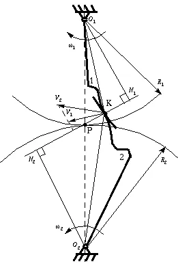
Figure 7-2 Two gearing tooth profiles
Although the two profiles have different velocities V1 and V2 at point K, their velocities along N1N2 are equal in both magnitude and direction. Otherwise the two tooth profiles would separate from each other. Therefore, we have
 (7-1)
(7-1)
or
 (7-2)
(7-2)
We notice that the intersection of the tangency N1N2 and the line of center O1O2 is point P, and
 (7-3)
(7-3)
Thus, the relationship between the angular velocities of the driving gear to the driven gear, or velocity ratio, of a pair of mating teeth is
 (7-4)
(7-4)
Point P is very important to the velocity ratio, and it is called the pitch point. Pitch point divides the line between the line of centers and its position decides the velocity ratio of the two teeth. The above expression is the fundamental law of gear-tooth action.
Constant Velocity Ratio
For a constant velocity ratio, the position of P should remain unchanged. In this case, the motion transmission between two gears is equivalent to the motion transmission between two imagined slipless cylinders with radius R1 and R2 or diameter D1 and D2. We can get two circles whose centers are at O1 and O2, and through pitch point P. These two circle are termed pitch circles. The velocity ratio is equal to the inverse ratio of the diameters of pitch circles. This is the fundamental law of gear-tooth action.
The fundamental law of gear-tooth action may now also be stated as follow (for gears with fixed center distance) (Ham 58):
The common normal to the tooth profiles at the point of contact must always pass through a fixed point (the pitch point) on the line of centers (to get a constant velocity ration).
Conjugate Profiles
To obtain the expected velocity ratio of two tooth profiles, the normal line of their profiles must pass through the corresponding pitch point, which is decided by the velocity ratio. The two profiles which satisfy this requirement are called conjugate profiles. Sometimes, we simply termed the tooth profiles which satisfy the fundamental law of gear-tooth action the conjugate profiles.
Although many tooth shapes are possible for which a mating tooth could be designed to satisfy the fundamental law, only two are in general use: the cycloidal and involute profiles. The involute has important advantages — it is easy to manufacture and the center distance between a pair of involute gears can be varied without changing the velocity ratio. Thus close tolerances between shaft locations are not required when using the involute profile. The most commonly used conjugate tooth curve is the involute curve.


Comments are closed