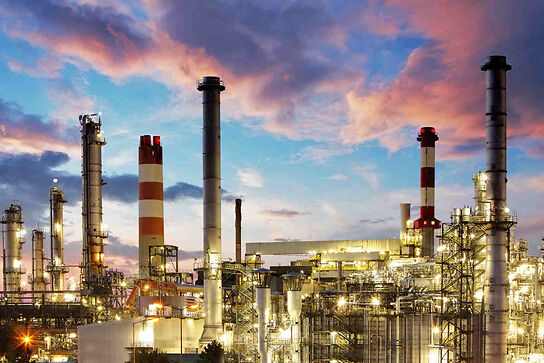
The crude oil is pumped ashore by the export oil pumps via undersea pipelines to a landfall as close to the crude oil refinery as possible. The hydrocarbons have been partially refined on the production platform and is now ready for refining into the final products such as diesel oil and petroleum.
Onshore Refining of Crude Oil
We started this series of the marine offshore oil & gas articles with the formation of oil and gas, and then we looked at the methods of finding it under the sea. Drilling and production methods followed this and now we are almost at the end the series with the final refining of the hydrocarbons. The last article will be on decommissioning the production platforms and abandoning the reservoir.
However, back to the present, the oil has eventually arrived at the onshore refinery, either directly from the various production platforms, by continued pipeline from the subsea landfall or from oil tankers which berth quite close to the refinery.
Refineries of crude oil, release a percentage of gas during oil refining process. In this article we shall examine the oil refining processes.
We shall start then with the arrival of crude oil, such as that wrestled from under the North Sea at a typical crude refinery.
The Desalter
The crude oil supplied to the refinery still contains a certain amount of water, and held in suspension in the water are various chlorides such as sodium, calcium and magnesium. If these salts are not removed they could prove harmful to equipment used further down the line by corrosion.
Once the salts have been removed the serious business begins as the oil enters the heaters before being piped to the vertical distillation unit.
Crude oil Heaters
The crude oil now requires to be heated and this is done in two stages. The first stage heater is known as the bottoms feed heater and from here the crude is passed to the furnace feed heater and piped to the atmospheric distillation unit.
Atmospheric Distillation Unit (ADU)
The ADU is a vertical vessel with horizontal perforated stainless steel trays spaced at specific intervals. The partially vaporised crude oil enters the vessel, the liquids falling to the base as bottoms and the vapours rising up the column, condensing on the trays into its different fractions at the pertinent temperatures and pressures. These fractions are then piped from their relevant stainless steel trays through condensers and on into holding tanks or passed on to the next process.
Some of the residue at the bottom of the ADU goes to storage as heavy fuel oil the remainder being reheated and passing into the Vacuum Distillation Unit (VDU).
Reflux Drum
The vapour at the very top of the ADU is directed to a reflux drum where the gas and liquids are separated, the reflux going back into the ADU and some of the gas bled off for plant use and the remainder being processed to LPG and Butane.
Isomerisation Plant
Here the light naphtha from the top tray of the ADU is passed through a Catalytic hydrotreater before being fed into the isomerisation unit. The naphtha is made up from a mixture of hexanes and pentanes which are isomerised by the H2when passing through the chlorided-alumina catalysts. The end product is high grade, low sulphur isomer, suitable for blending high octane gasoline.
Catalytic Reforming
This process converts low octane naphtha to gasoline blending and upgrading components by the simultaneous reactions of dehydrogenation, isomerisation and catalytic cracking, the catalyst used is normally platinum. The dehydration releases a quantity of hydrogen which is reused throughout the refinery.
The end product is a reformate high in the aromatics essential for final upgrading and blending of gasoline.
Merox Treater Unit
This is a sweetening process used to convert mercaptan sulphur found in kerosene.
After fractionalisation the kerosene passes through a caustic prewash then compressed air is injected into the fluids. The mixture now enters at the top of the reactor flowing downwards over a catalytic bed and passing onto the caustic settling tank. From here the mixture passes through another water wash then salt and clay filters before being filtered through clay filters and exiting as jet fuel.
This final filtration ensures that the jet fuel meets all the relevant specs, especially that of heavy metals and particulates.
.
Catalytic Hydrotreating Units (CHU)
From my process drawing of the refinery plant it can be seen that there are numerous CHU’s which are used as pretreatment processing units. Once again we see the combination of catalytic and hydrogen being used to remove or convert undesirable contaminates from the fractions. These contaminates must be removed as the fractions are processed as they would have a damaging effect on the refinery equipment, the different catalysts used and, the end products. Hydrotreating can also be used to upgrade certain low grade oils and convert aromatics to saturated amalgamations.
Fluid Catalytic Cracker. (FCC)
The light oils from the ADU and VDU pass through a pre treatment process which heats the gas oil, and injection hydrogen separating the gas from the oil. The oil is then mixed with a fluid catalyst before passing into the FCC unit itself which consists of the riser, reactor, regenerator and fractionating tower. The fluid state is maintained between the riser and the reactor by the vapour and injection of steam and combustion air into the riser. The fluids are cracked and the catalyst is separated from the fluids, the fluids passing to the fractionating tower for separation into the required fractions and the catalyst passing to the regeneration unit for decoking.
Residual Fuel (Heavy Fuel Oil)
Following the removal of the required factions we are left with a residue at the bottom of the column, known appropriately as ‘bottoms’
It is from these bottoms that Residual Fuel (Heavy Fuel Oil) is drawn off; the remainder of the bottoms is fed into the Vacuum Distillation Unit where they are further treated under vacuum, and is discussed in the next section.
The sulfur content at this stage of processing can be as high as 6%mm and must undergo further processing to reduce the content to IMO 2010 regulations of 4.5%. This process is described in another article but is carried out by reformation using catalysts in fixed bed reactors, gas separators and strippers, as shown in the images section.
Vacuum Distillation Unit (VDU)
The heavy oil from the ADU bottoms is now reheated and pumped into the VDU which is maintained at 2″Hg.
There are two factions from the VDU these being vacuum light gas oil and vacuum heavy gas oil. The light oil joins the gas oil from the ADU and is passed through a catalytic cracker, the heavy oil being pumped through the hydrocracker. The bottoms residue are pumped to the delayed coke unit and asphalt processing unit.
Hydrocracking
The heavy vacuum gas oil from the vacuum distillation unit is processed by hydrocracking, a combination of catalyst cracking and hydrogenation. The unit also serves as an isomerisation processor improving the pour and low smoke properties of the end product of jet fuel and gas oil.
The injected hydrogen preserves the catalyst preventing coking but also reacts with the sulphur and nitrogen in the heavy vacuum oil converting these to hydrogen sulphide and ammonia.
The alkylation feedstock output from the hydrocracking is also a very important ingredient used in the upgrading and blending of petroleum.
Delayed Coking
Another product from the Vacuum Distillation Unit bottoms is naphtha and coke light oil.
The residue is passed through a series of heaters raising the temperature to almost1000ºF. The residue is now fed into coke bins where it remains for up to 24hrs until it is converted to lighter oils due to the cracking reactions taking place. The vapours from the bins are fed into a fractionator tower where the fractions of gas, naphtha and light oils are separated out.
Asphalt, a byproduct of the VDU bottoms is used in roof waterproofing and road surfacing.
Oil Refining Sketches


