This incident happened on a cruise liner with diesel electric propulsion. The main generator engines are 4 x MAN B&W 14 cylinder V48/60 medium speed engines each with a maximum output of 13650kW at 514rpm..
The main engines drive alternators which generate 3 phase electricity at 6,600V. This is transformed to 3900 volts for main propulsion and 690 volts for some auxiliary machinery motors. It is also transformed to 240 volts for domestic use. The alternators are each rated at 17500kVA, 1531 amps with a power factor of 0.8.
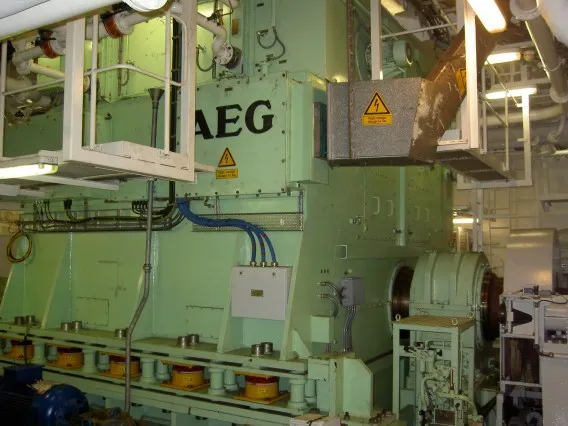
The main propulsion motors are 2 × AEG 20MW 3900 volt synchronous motors (each wound as two half motors) rotating at up to 140 rpm, driving conventional propeller shafts and fixed pitch propellers. The motor speed is varied using synchro converters which alter the frequency between 0 and 18.67Hz
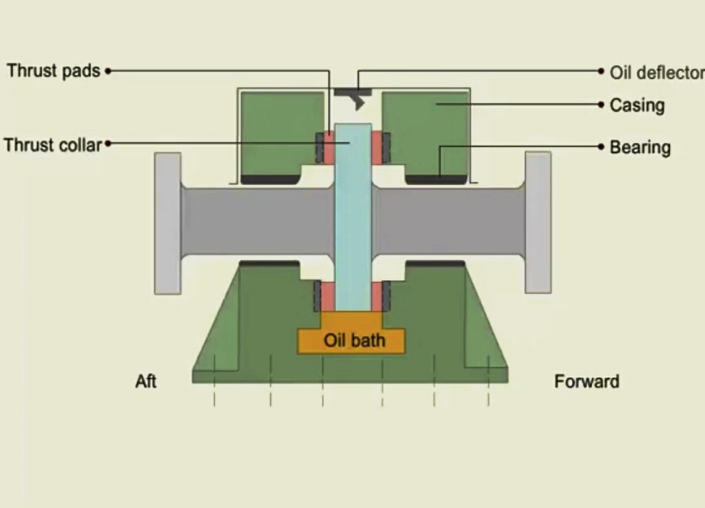
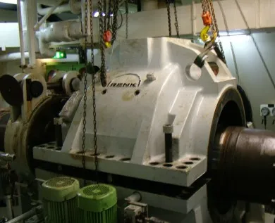
As with any propulsion system the thrust from the propeller must be transmitted into the hull to drive the ship through the water. The thrust bearings in this case are mounted aft of the propulsion motors before the shaft bearings (plummer blocks). There is a shaft brake situated between thrust bearing and propulsion motor and a shaft locking device aft of the thrust bearing. Manufactured by Renk the thrust pads are not of the typical kidney shape but are circular. There are 12 pads each of 225mm diameter on either side of the thrust collar which is 1140mm in diameter and 200mm thick. Like the traditional kidney shaped pads, these pads are faced with white metal and tilt to allow an oil wedge to be built up so there is no metal to metal contact.
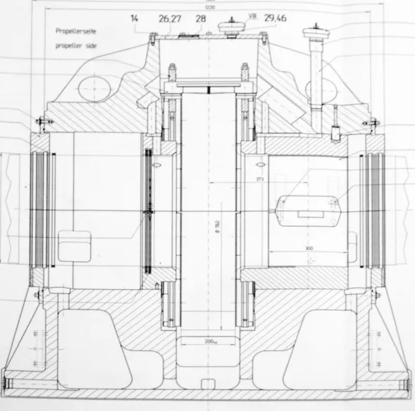
Sectional Drawing Through Thrust Block
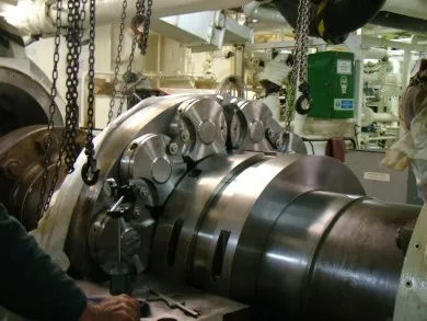
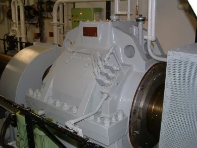 Stbd Side Thrust Block in Normal Use Stbd Side Thrust Block in Normal Use | 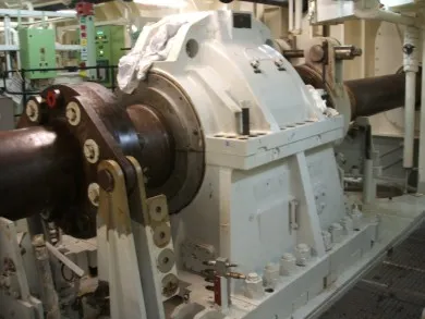 Port Side Thrust Block Prior to Lifting With Shaft Brake and Locking Device Engaged Port Side Thrust Block Prior to Lifting With Shaft Brake and Locking Device Engaged |
The vessel was on passage when the port thrust bearing high temperature alarm sounded. Instead of reducing speed and stopping the propulsion motor, the watchkeeper kept it running whilst detailing the junior watchkeeper to take a look. The alarm went open circuit, as the tip of the probe was taken off by the thrust collar. The propulsion motor was eventually stopped when the junior watchkeeper reported back that the bearing was overheating. By then the damage was extensive.
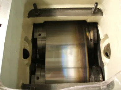 Thrust Collar and Pads Through Inspection Cover Thrust Collar and Pads Through Inspection Cover | 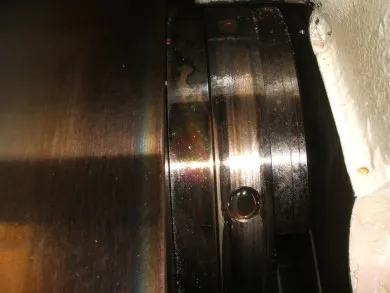 Close up of Ahead Pad and Thrust Collar through Inspection Cover Close up of Ahead Pad and Thrust Collar through Inspection Cover |
Opening up the inspection cover, the ahead thrust face could be seen to have been seriously over heated, with the white metal melted from the ahead pads which are also discoloured.
With the shaft locked, the vessel proceeded to the next port on the Stbd propulsion motor. Specialists from Renk and classification surveyor came on board.
To remove the pads and the adjacent shell bearing, the top cover was lifted.
 Lifting Cover Lifting Cover | 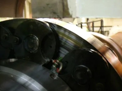 Ahead Thrust Face and Pads Ahead Thrust Face and Pads |
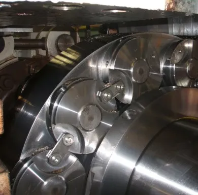 Astern Pads and Collar Showing How Pads Are Linked.Note White Metal Debris Astern Pads and Collar Showing How Pads Are Linked.Note White Metal Debris | 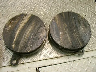 Wiped Ahead Pads Wiped Ahead Pads |
 Turning Out Bottom Half of Shell Bearing After Jacking Shaft Turning Out Bottom Half of Shell Bearing After Jacking Shaft | 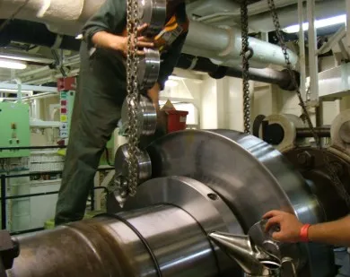 Removing Astern Thrust Pads Removing Astern Thrust Pads |
The astern pads and the lower shell bearing sustained minor damage which was scraped out.
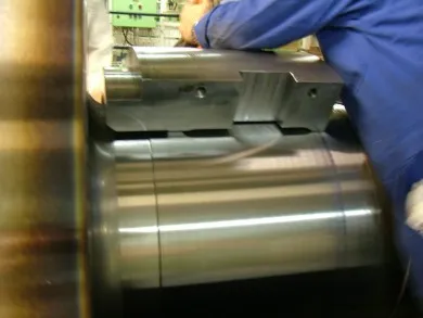
The ahead thrust face was ground and new pads fitted.
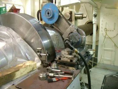 Grinder Set Up Grinder Set Up | 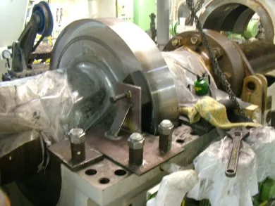 Temporary Thrust Arrangement To Prevent Fwd Movement of Shaft Temporary Thrust Arrangement To Prevent Fwd Movement of Shaft |
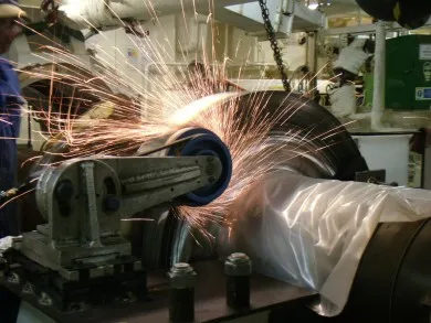 Grinding of Ahead Thrust Face Grinding of Ahead Thrust Face |  Crack Detecting Crack Detecting |
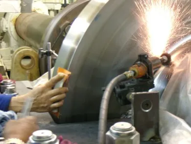 Grinding Radius Grinding Radius | 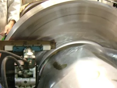 Polishing Ahead Face Polishing Ahead Face |
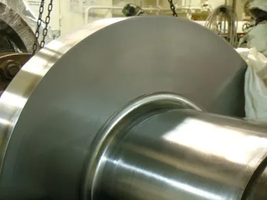 Finished Ahead Face Finished Ahead Face | 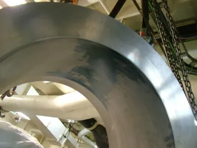 Lowering Lower Half Shell Bearing Lowering Lower Half Shell Bearing |
 Ahead Pads Refitted Ahead Pads Refitted | 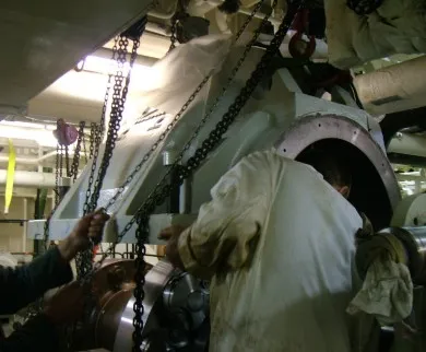 Lowering Cover Lowering Cover |
Comments are closed