The propeller consists of a boss with several blades of helicoidal form attached to it. When rotated it ‘screws’ or thrusts its way through the water by giving momentum to the column of water passing through it. The thrust is transmitted along the shafting to the thrust block and finally to the ship’s structure.
A solid fixed-pitch propeller is shown in Figure above. Although usually described as fixed, the pitch does vary with increasing radius from the boss. The pitch at any point is fixed, however, and for calculation purposes a mean or average value is used.
A propeller which turns clockwise when viewed from aft is considered right-handed and most single-screw ships have right-handed propellers. A twin-screw ship will usually have a right-handed starboard propeller and a left-handed port propeller.
Propeller mounting
The propeller is fitted onto a taper on the tailshaft and a key may be inserted between the two: alternatively a keyless arrangement may be used. A large nut is fastened and locked in place on the end of the tailshaft: a cone is then bolted over the end of the tailshaft to provide a smooth flow of water from the propeller.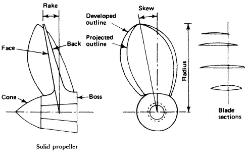
Fig: A solid fixed-pitch propeller
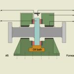
One method of keyless propeller fitting is the oil injection system. The propeller bore has a series of axial and circumferential grooves machined into it. High-pressure oil is injected between the tapered section of the tailshaft and the propeller. This reduces the friction between the two parts and the propeller is pushed up the shaft taper by a hydraulic jacking ring. Once the propeller is positioned the oil pressure is released and the oil runs back, leaving the shaft and propeller securely fastened together.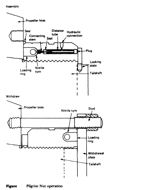
Fig: Pilgrim Nut Operation
The Pilgrim Nut is a patented device which provides a predetermined frictional grip between the propeller and its shaft. With this arrangement the engine torque may be transmitted without loading the key, where it is fitted. The Pilgrim Nut is, in effect, a threaded hydraulic jack which is screwed onto the tailshaft (Figure above). A steel ring receives thrust from a hydraulically pressurised nitrile rubber tyre. This thrust is applied to the propeller to force it onto the tapered tailshaft. Propeller removal is achieved by reversing the Pilgrim Nut and using a withdrawal plate which is fastened to the propeller boss by studs. When the tyre is pressurised the propeller is drawn off the taper. Assembly and withdrawal are shown in Figure above.
Cavitation
Cavitation, the forming and bursting of vapour-filled cavities or bubbles, can occur as a result of pressure variations on the back of a propeller blade. The results are a loss of thrust, erosion of the blade surface, vibrations in the afterbody of the ship and noise. It is usually limited to high-speed heavily loaded propellers and is not a problem under normal operating conditions with a well designed propeller.
Propeller maintenance
When a ship is in dry dock the opportunity should be taken to thoroughly examine the propeller, and any repairs necessary should be carried out by skilled dockyard staff.
A careful examination should be made around the blade edges for signs of cracks. Even the smallest of cracks should not be ignored as they act to increase stresses locally and can result in the loss of a blade if the propeller receives a sharp blow. Edge cracks should be welded up with suitable electrodes.
Bent blades, particularly at the tips, should receive attention as soon as possible. Except for slight deformation the application of heat will be required. This must be followed by more general heating in order to stress relieve the area around the repair.
Surface roughness caused by slight pitting can be lightly ground out and the area polished. More serious damage should be made good by welding and subsequent heat treatment. A temporary repair for deep pits or holes could be done with a suitable resin filler.