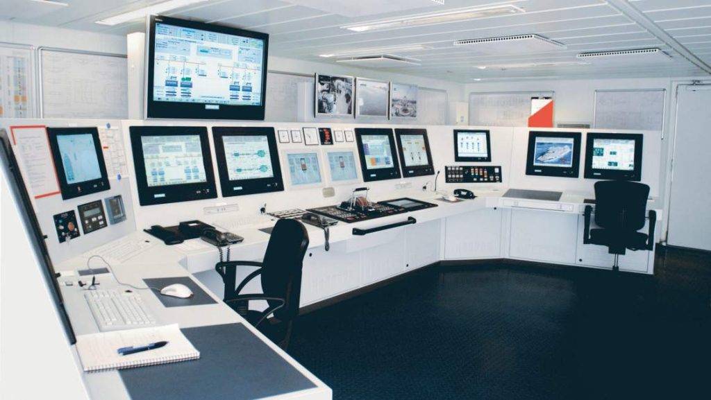
The alarm monitoring and control system on the ship may give false alarms and incorrect data printouts. These faults could be:
1. Localized to a particular area of engine operation or
2. General to the engine room
When the alarms are specific to a certain area of the engine room it would be suspected that the following faults could be present
· Cable fault: If the cable connecting the sensors with the control room were damaged, the resulting short/open circuits could generate false alarms
· Control card/panel fault: The alarms could be grouped within a certain alarm or monitoring panel, and there could be a defect within this panel.
· External interference: Machinery could be operating in the suspect area, which is poorly screened, and the resulting interference could be transmitted via the instrument cables to the monitoring panels.
When the alarms are general to the whole engine room, then the main supply to the alarm and monitoring panel would be checked for:
· Earth faults: A combination of earth faults could affect the earth potential and hence the reading of the instrumentation.
· Supply voltage level: The monitoring circuit would use low 24V supply, and this would need to be at the correct level without any voltage ripple present.
The following action should be taken to ensure continued safe operation of the vessel if the defects with alarm monitoring and control system were general to the engine room.
· The problem with intermittent alarms and incorrect printouts would be that the engineer on duty would be unable to rely on the information given to him by the remote instrumentation and alarm panel. Hence a greater use would need to be taken of the local readings from pressure gauges and thermometers.
· This would mean that the UMS operation would be stopped and watch-keeping practices with a manned engine room would be commenced. The watch keepers would be instructed to complete a full manual log of the various operational parameters of pressure, temperature and the various tank levels. This manual log would be taken every watch period of four hours.
· The engineering staff would be divided between the various watch duties, ensuring that all watch keepers were certified and had the appropriate duty and rest periods assigned to them.
· Any machinery units requiring manual control would have their operation explained to all engineers, and a procedural checklist compiled for the operation of all such machinery.
Troubleshooting Alarm Monitoring and Control System
The possible faults stated earlier would be the earth fault or supply irregularity. The earth fault could be identified by observing the 24V distribution panel that would have an earth detection unit fitted. If an earth fault was indicated on this panel then
· A positive earth would be traced by disconnecting the supply fuses in turn to parts of the engine room to identify the problem area
· A negative earth would require that each instrument have its earth wire disconnected and left disconnected until the fault is traced. This would mean the loss of many of the instruments within the engine room and could only be carried out when watch keeping duties were active. Each wire would be marked to ensure correct replacement.
· The supply irregularity could be identified by using an oscilloscope, which would show both the level of voltage present and if any supply ripple was present. A simple AVO meter would also indicate correct voltage levels. The earth fault would be rectified by locating the cable/insulation defect and then replacing the cable, or repairing the defect by re-insulating the damaged area. The supply irregularity would be rectified by replacing the charging unit of the 24V DC supply, and/or replacing any defective batteries.


