
This article gives you the concept of a simple fluid mechanics experiment using Pascal’s law as a principle. Also read a discussion of the calculation related to the experiment and an example application in the hydraulic steering system that is employed on board a ship for steering.
This article gives you the concept of a simple fluid mechanics experiment and its calculation as is used in the marine field and other fields involving hydraulics. The fluid mechanics experiment concept described below is used in the hydraulic steering gear system employed onboard ship for steering the ship either towards starboad or port. This simple fluid mechanics experiment is based on the principle of Pascal’s law.
Fluid Mechanics Experiment:
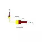
Consider a fluid system consisting of two cylinders of different diameters. One cylinder is of large diameter and contains a ram in it that can be moved up and down. Another cylinder is of small diameter and contains a plunger that can move in it. The large diameter cylinder and small diameter cylinder are connected by a pipe of suitable thickness in order to withstand the pressure created inside. The cylinders and pipe contain liquid or hydraulic oil through which the pressure can be transmitted.
When a small force is applied on a plunger (in the case of a hydraulic steering gear, this is located in the navigation bridge of a ship and force can be applied by rotating the steering wheel either clockwise or counterclockwise – see the sketch below) in a downward direction, a pressure is produced on the liquid in contact with the plunger. This pressure is transmitted equally in all directions and acts on the large diameter ram to move it.
It has been seen that the movement of the plunger in the small cylinder due to the small force applied displaces the hydraulic fluid in it. Since the hydraulic fluid or oil cannot be compressed inside the cylinder, pressure will build up inside the cylinder which depends upon the force applied and the diameter of the plunger. The pressure that has been created inside the cylinder will act equally in all directions as stated by pascal’s law. The same pressure will now act on the ram that is in contact with the hydraulic fluid.This will exert a force on the ram and now the ram moves in the desired direction corresponding to the force applied. The force which is moving the ram will depend upon the diameter of the ram and the pressure developed in the hydraulic fluid due to the force applied manually on the plunger. Finally, the force applied manually (input to the system) on the plunger is converted into the desired movement on the ram which is the output of the system.
Simple Experiment Using Pascal’s Law
Practical Example
Calculations Related to above Experiment
○ Let f1 be the force applied on the plunger and
○ f2 be the force acting on the ram.
○ Let A1 be the area of the plunger and
○ A2 be the area of the ram.
○ p will be the intensity of pressure produced by the force f1.
therefore,
pressure intensity produced by the force f1 = (force applied on the plunger f1) / (area of the plunger A1)
As per Pascal’s law, the intensity of pressure in a static fluid is transmitted equally in all directions, so the above intensity of pressure produced by the plunger will be equally transmitted in all directions. Therefore the pressure intensity at the ram will be equal to the force applied on the plunger f1 divided by area of the plunger A1.
Also pressure intensity on the ram = (force acting on ram f2) / (area of the ram A2).
Equating the pressure intensity on the ram, we get
(f1 / A1) = (f2 / A2).
The total force acting on the ram f2 = (force applied on the plunger f1 × area of the ram A2) / area of the plunger A1
Example for the above Derivation
For Example,
Let us consider a ram of 300 mm diameter to be moved, the diameter of plunger is 20mm, and the force applied on the plunger is 100N.
Then the Force available at the ram = (Force applied on the plunger × Area of the ram) / Area of the plunger
Area of the ram = ( 3.14×0.32 ) / 4
Area of the ram=0.07068 mm2
Area of the plunger or piston = ( 3.14 ×.022 ) / 4
Area of the plunger or piston =0.00031 mm2
Force available at the ram = (100 × 0.07068 ) / 0.00031
Force available at the ram =22509.55 N
From the above example, it is clear that the force applied manually on the system is only 100N and this is converted to 22510N approximately which can be able to operate the heavy system that cannot be operated manually.
Application in the Field
The above explained simple experiment is used in hydraulic steering gear with some special arrangements. The small movement of the steering wheel in the navigation bridge may actuate the rudder to turn towards starboard or port side due to oil pressure acting on the ram.
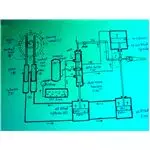
Hydraulic Steering Gear
Working of the Hydraulic Steering Gear
When the wheel 1 (usually called a steering wheel) is turned anticlockwise, the pinion 2 moves the toothed rack 3 downward and moves the toothed rack 4 upward. As it is fixed to the two piston 5 and 6, the piston also moves correspondingly. As these two cylinders 7 & 8 are filled with oil, the movement of the pistons result in oil pressure being applied to the bottom of the piston 10 and moves it upward and these forces the oil in upper part of cylinder 9 up in to the cylinder 8.
Piston 10 has a piston rod connected to a slide valve 11. In its middle position, the slide valve just closes the ports 12, 13, 14 in the slide valve housing 15. As the piston 10 moves upward, the slide valve 11 also moves along with it and opens port 12 and 14. These cause oil from the pressure vessel to come under side of the piston 20 and the oil above piston 20 is forced in to the slide valve housing 15 and out through the port 12 to the discharge tank 16. As a result the piston 21 moves upward along with the piston 20 since both these piston are connected together by piston rod. These upward movements of the two pistons impart movement to the tiller arm which is mounted on the rudder stock and hence moves the rudder.
Conclusion:
Here we have seen how Pascals law is used in hydraulic steering gear system employed onboard for steering a ship. The main basic principle of this experiment is that intensity of pressure exerted by hydraulic fluid is equal in all directions.