The hydraulic and pneumatic elements such as cylinders and valves are connected through pipelines to form a hydraulic or a pneumatic circuit. It is difficult to represent the complex functioning of these elements using sketches. Therefore graphical symbols are used to indicate these elements. The symbols only specify the function of the element without indicating the design of the element. Symbols also indicate the actuation method, direction of flow of air and designation of the ports. Symbols are described in various documents like DIN24300, BS2917, ISO1219 and the new ISO5599, CETOP RP3 and the original American JIC and ANSI symbols.
The symbol used to represent an individual element display the following characteristics:
· Function
· Actuation and return actuation methods
· Number of connections
· Number of switching positions
· General operating principle
· Simplified representation of the flow path
The symbol does not represent the following characteristics:
· Size or dimensions of the component
· Particular manufacturer, methods of construction or costs
· Operation of the ports
· Any physical details of the elements
· Any unions or connections other than junctions
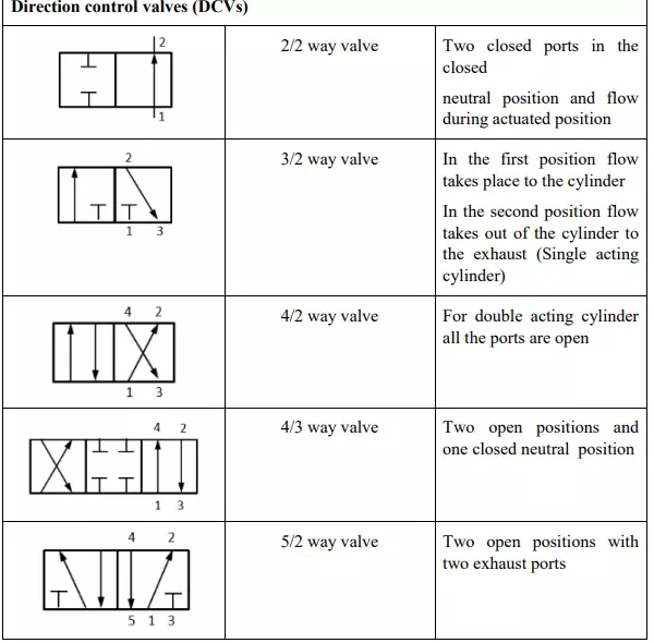
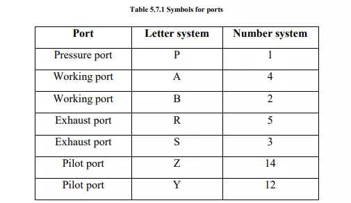
Earlier the ports were designated with letter system. Now as per ISO5599 the ports are designated based on number system. The port designations are shown in table 5.7.1
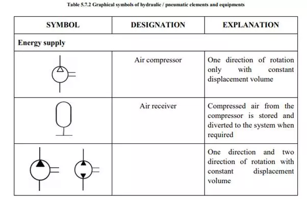
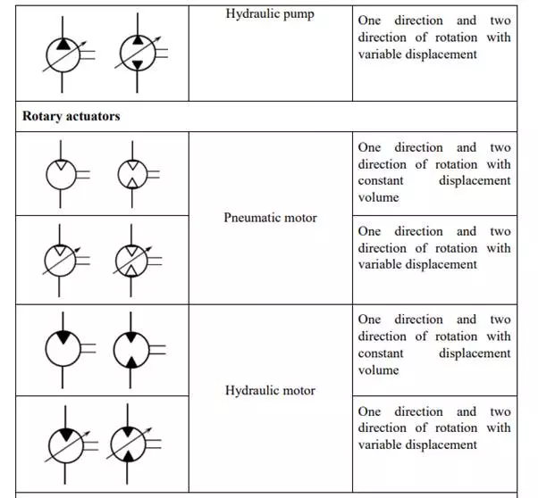
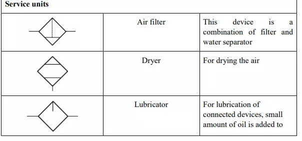
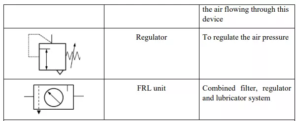
The graphical representation, designation and explanation of various components and equipments used in hydraulic and pneumatic system are given in table 5.7.2. Readers are suggested to study these representations carefully.