There are several valves on the cylinder heads of a marine diesel engine; the relief valve being one of these.
The role and construction of the relief valve on marine engine cylinders is examined in the following sections.
The first section gives an overview of a typical marine diesel cylinder head, including its valves and other components.
Typical Marine Diesel Cylinder Head
The cylinder head we will examine is typical of a large 2-stroke diesel engine having scavenge air inlet ports in the cylinder liner and an exhaust valve in the cylinder head. This is known as uniflow scavenging. Those cylinder heads without exhaust valves have exhaust ports cut into the top end of the liner above the inlet ports, being known as loop scavenging engines.
The cylinder head contains the following components;
§ Fuel Valves
These inject the heavy fuel oil and diesel oil as a mist into the combustion chamber, being controlled nowadays by the common rail fuel system.
§ Air-start Valve
This is used to start the engine in the ahead or astern rotation by injecting compressed air into the relative cylinder.
§ Exhaust Gas Valve
This is contained in a cage fitted into an insert in the cylinder head. Modern exhaust valves are placed at the centre of the cylinder head having a water cooled cage, the valve being hydraulically operated rather than by a pushrod. They can also have a “fin” welded to the valve stem; the exhaust gas rotating the valve thus decreasing the wear on the seat.
§ Indicator Cock
This valve has two purposes
1. To enable indicator cards to be taken; these show the condition of the engine under normal operating conditions.
2. They are opened whilst engine is turned over on air for a few rotations to blow out any dirt or water accumulated after engine has been shut-down for a while or overhauled. The cocks are then shut and the engine started normally. Remember; indicator cocks should always be left opened when rotating the main engine using the turning gear.
§ Cylinder Relief Valve
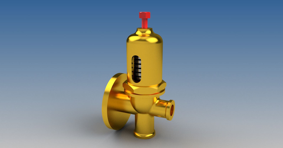
Main purpose is to lift when over pressure occurs in the combustion area; the resultant combustion gas being expelled to a through a flanged pipe to deck.
A sketch of a typical 2-stroke cylinder head is shown below; please click on image to enlarge.
Construction
The relief valve is enclosed within a cast iron casing that is secured to the cylinder head by threaded studs and hex nuts. It consists of the following components;
§ Helical Valve Spring
The spring is normally manufactured from silicon-chrome/vanadium spring wire that has been hardened and tempered in oil to the relative standards.
It is fitted inside the casing being held in position by the top and bottom ring keeps.
§ The Valve and Stem
The valve and stem are manufactured from high grade stainless steel, the valve being seated on an integral seat/machined landing that is open to the combustion chamber. The stem is not connected to the valve, but sits atop of it; protruding through the centre of the spring and terminating in a threaded portion outside the top of the casing. The threaded portion contains the locknuts that are used to adjust the spring tension, via the top spring collar. This allows the lifting pressure of the valve to be set at 20% over maximum internal combustion pressure.
Maintenance consists of cleaning and inspecting all the components at the same intervals as cylinder head overhaul. The valve seat should be examined and re-ground; the spring being checked for cracks and its free length measured under no-load conditions.
After the assembly the valve should be set to the correct lifting pressure before being subjected to pressure and leak testing.
At Harland and Wolff; we used to leak-test the seat by pouring paraffin oil into the valve casing. Any sign of a leak-no matter how insignificant and the valve was stripped, the seat reground then retested. Pressure testing was carried out on a bench mounted test rig consisting of a high pressure air compressor, air pressure control valve, and calibrated gauges. The relief valve was bolted to the compressor accumulator flange and the air pressure increased until the valve lifted. The certifying authority at the time was DNV and Lloyds of London and they witnessed the testing of every one we assembled before they were bolted to the cylinder heads of the engines. Mind you, that was 1964, but I suppose the setting and testing procedures are much the same today.
A sketch showing the components of a typical cylinder relief valve is shown below; please click on image to enlarge.

Operating Principles
“Normal” lifting of the relief valve can occur in the following situation, and should give no cause for concern;
§ When too much fuel is supplied by the engineer when on starting the engine; I have done this a few times!
§ If air is being used to stop engine in “emergency stop” situation.
§ Running engine full astern for a prolonged period, in this case the bridge should be informed that astern running is at its limit.
However, there are situations that could lead to a relief valve lifting while engine is operating under normal load and conditions and warrant a full inspection.
§ Faulty fuel pump or incorrectly set fuel injector delivering excessive fuel.
§ Badly leaking fuel injector; through loose nozzle or enlarged injection holes.
§ Water leaking into the combustion chamber.
§ Scavenge fire.


