To find out the accuracy of a screw thread it will be necessary to measure the following:
1. Major diameter.
2. Minor diameter.
3. Effective or Pitch diameter.
4. Pitch
5. Thread angle and form
1. Measurement of major diameter:
The instruments which are used to find the major diameter are by
· Ordinary micrometer
· Bench micrometer.
· Ordinary micrometer
The ordinary micrometer is quite suitable for measuring the external major diameter. It is first adjusted for appropriate cylindrical size (S) having the same diameter
(approximately).Thisge processsetting’is. Afterknown takias‘ micrometer is set on the major diameter of
· Bench micrometer
For getting the greater accuracy the bench micrometer is used for measuring the major diameter. In this process the variation in measuring Pressure, pitch errors are being neglected. The fiducial indicator is used to ensure all the measurements are made at same pressure. The instrument has a micrometer head with a vernier scale to read the accuracy of 0.002mm. Calibrated setting cylinder having the same diameter as the major diameter of the thread to be measured is used as setting standard. After setting the standard, the setting cylinder is held between the anvils and the reading is taken. Then the cylinder is replaced by the threaded work piece and the new reading is taken.
Fig 3.6 Bench Micrometer
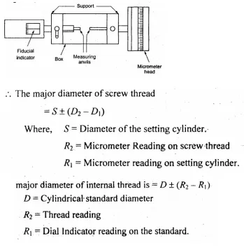
· Measurement of the major diameter of an Internal thread
The Inter thread major diameter is usually measured by thread comparator fitted with ball-ended styli. First the Instrument is set for a cylindrical reference having the root of spring under pressure. For that the new reading is taken.
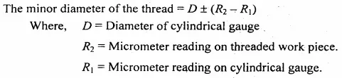
2. Measurement of Minor diameter
The minor diameter is measured by a comparative method by using floating carriage diameter measuring machine and small V pieces which make contact with the root of the thread. These V pieces are made in several sizes, having suitable radii at the edges. V pieces are made of hardened steel. The floating carriage diameter-measuring machine is a bench micrometer mounted on a carriage.
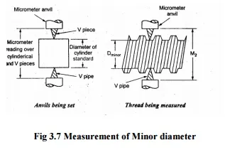
Fig 3.7 Measurement of Minor diameter
· Measurement process
The threaded work piece is mounted between the centers of the instrument and the V pieces are placed on each side of the work piece and then the reading is noted. After taking this reading the work piece is then replaced by a standard reference cylindrical setting gauge.
· Measurement of Minor diameter of Internal threads
The Minor diameter of Internal threads are measured by
1. Using taper parallels
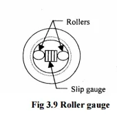
2. Using Rollers.
· Using taper parallels
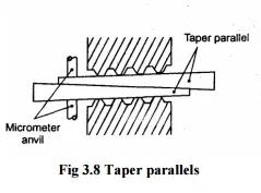
For diameters less than 200mm the use of Taper parallels and micrometer is very common. The taper parallels are pairs of wedges having reduced and parallel outer edges. The diameter across their outer edges can be changed by sliding them over each other.
· Using rollers
For more than 20mm diameter this method is used. Precision rollers are inserted inside the thread and proper slip gauge is inserted between the rollers. The minor diameter is then the length of slip gauges plus twice the diameter of roller.
3. Measurement of effective diameter
Effective diameter measurement is carried out by following methods.
1. One wire,
2. Two wires, or
3. Three wires method.
4. Micrometer method.
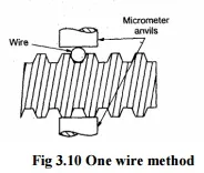
a) One wire method
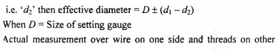
The only one wire is used in this method. The wire is placed between two threads at one side and on the other side the anvil of the measuring micrometer contacts the crests. First the micrometer reading dl is noted on a standard gauge whose dimension is approximately same to be obtained by this method
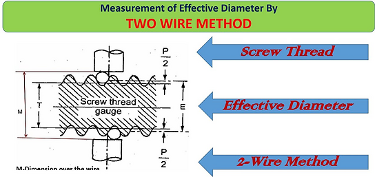
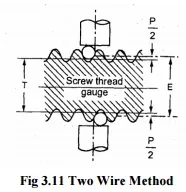
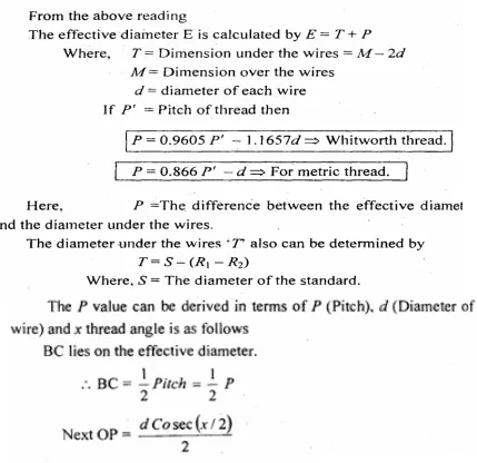
b) Two wire method
Two-wire method of measuring the effective diameter of a screw thread is given below. In this method wires of suitable size are placed between the standard and the micrometer anvils. First the micrometer reading is taken and let it be R. Then the standard is replaced by the screw thread to be measured and the new reading is taken.
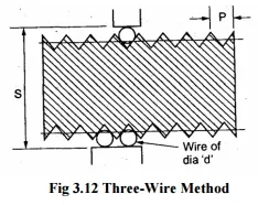
c) Three-Wire method
The three-wire method is the accurate method. In this method three wires of equal and precise diameter are placed in the groves at opposite sides of the screw. In this one wire on one side and two on the other side are used. The wires either may held in hand or hung from a stand. This method ensures the alignment of micrometer anvil faces parallel to the thread axis.
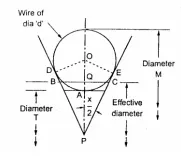
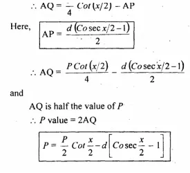
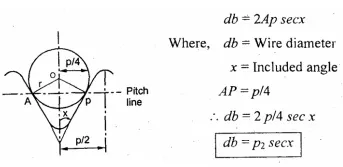
· BEST WIRE SIZE-DEVIATION
Best wire diameter is that may contact with the flanks of the thread on the pitch line. The figure shows the wire makes contact with the flanks of the thread on the pitch.
Hence best wire diameter,
4. Pitch measurement
The most commonly used methods for measuring the pitch are
1. Pitch measuring machine
2. Tool maker’s microscope
3. Screw pitch gauge
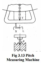
· Pitch measuring machine
The principle of the method of measurement is to move the stylus along the screen parallel to the axis from one space to the next. The pitch-measuring machine provides a relatively simple and accurate method of measuring the pitch. Initially the micrometer reading is near the zero on the scale, the indicator is moved along to bring the stylus, next the indicator adjusted radially until the stylus engages between the thread flank and the pointer ‘K’ is opposite Measuring Machine line in its index mark a small movement is necessary in the micrometer and then the reading is taken next. The stylus is moved along into the next space by rotation of the micrometer and the second reading is taken. The difference between these two- measured readings is known as the pitch of the thread.
• Tool makers microscope
Working
Worktable is placed on the base of the base of the instrument. The optical head is mounted on a vertical column it can be moved up and down. Work piece is mounted on a glass plate. A light source provides horizontal beam of light which is reflected from a mirror by 900 upwards towards the table. Image of the outline contour of the work piece passes
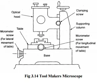
through the objective of the optical head. The image is projected by a system of three prisms to a ground glass screen. The measurements are made by means of cross lines engraved on the ground glass screen. The screen can be rotated through 360°. Different types of graduated screens and eyepieces are used.
· Applications
· Linear measurements.
· Measurement of pitch of the screw. o Measurement of pitch diameter.
· Measurement of thread angle. o Comparing thread forms.
· Centre to center distance measurement.
· Thread form and flank angle measurement
· Thread form and flank angle measurement
The optical projections are used to check the thread form and angles in the thread. The projectors equipped with work holding fixtures, lamp, and lenses. The light rays from the lens are directed into the cabinet and prisons and mirrors. The enlarged image of thread is drawn. The ideal and actual forms are compared for the measurement.
Comments are closed