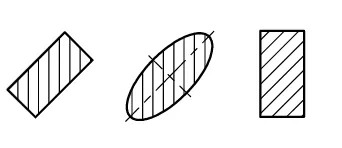
Hatching is generally used to show areas of sections. The simplest form of hatching may be based upon continuous thin lines at a convenient angle, preferably 45°, to the principle outlines of symmetry of sections.
Hatching may be used to indicate type of materials, in sections. If different types of hatching are used to indicate different materials, the meaning of this hatchings shall be clearly defined on the drawing, or by reference to appropriate standards.
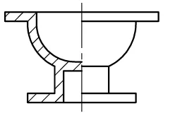
Full sections
When the cutting plane extends entirely through the object in a straight line and the front half of the object is theoretically removed, a full section is obtained. This type of section is used for both detail and assembly drawings. When the cutting plane divides the object into two identical parts, it is not necessary to indicate its location.
Offset sections
This type of sectioned view appears to be a full section. In order to include features that are not in a straight line, the cutting-plane line may be offset or bent, so as to include several planes or curved surfaces.
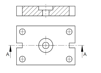
Half Sections
Symmetrical parts may be drawn half in section and half in outside view. This type of drawing avoids the necessity of introducing dotted lines for the holes and the recess. Dimensioning to dotted lines is not a recommended practice.
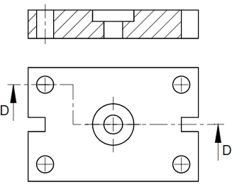
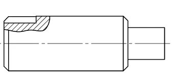
Local sections
It is not always necessary to draw a complete section through a component if a small amount of detail only needs to be illustrated. The local section or broken-out section of a view has the appearance of having been hit with a hammer to break a small part from the object. Rather than create a section through the entire part, only a localized portion of the object is sectioned.
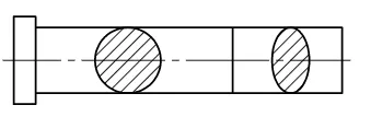
Revolved sections
A revolved section is shown the shape of the cross section at that point. This is a convenient convention to use on single view drawings because the shape could not be confirmed without projecting a second view or an added note.
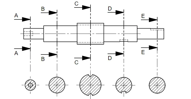
Successive sections
Successive sections may be arranged as convenient for the layout and understanding of the drawing. Note that where successive sections are drawn, each view only gives the detail at that section plane and not additional background information.
Thin sections
Many products are manufactured from very thin materials which would be virtually impossible to cross hatch in a sectional view and in these cases it is usual to make them entirely black. Where however two or more thin sections are adjacent to each other, a gap is left so that the profile of the separate components is clearly defined. A space of not less than 0.7 mm must be left between adjucent sections of this type.