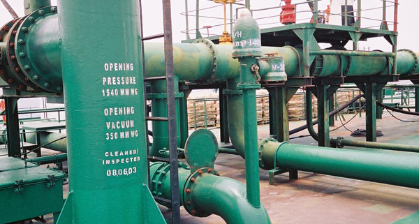
Cargo tanks of a chemical tanker are required to be provided with venting systems to prevent both over and under pressurisation of the tank. Two types of venting system are specified by the Code, namely “open” and “controlled”.
Open tank venting system – An open venting system is for cargoes which are of little or no flammable or toxic hazard.

Fig: Pressure-vacuum valves on a chemical tanker
Controlled tank-venting system – Controlled venting systems are required to be fitted in all tanks carrying cargoes emitting harmful or flammable vapours. Each tank must be fitted with pressure/vacuum valve to relieve over-pressure or under-pressure.
Venting of cargo tanks during cargo transfer or cargo related operations must be carried out in accordance with applicable international, national, port and terminal regulations. On chemical tankers the general rule is that the primary venting system is PV valves and the secondary means are cargo tanks pressure monitoring system.
Tank vent system outlets are located at a safe distance from all areas where personnel who are not involved in cargo work may be present, to ensure that toxic vapours are diluted to a safe level of concentration before they can reach such an area. The safe distances specified depend on the severity of the toxic hazard. In all cases the principles described in the IMO Codes will have been met by the ship’s design.

Fig: Cargo tanks venting arrangement- SOLAS requirement
The cargo tank venting system should be set for the type of operation to be performed. Cargo vapour displaced from tanks during loading or ballasting should be vented through the installed venting system to atmosphere, except when return of the vapour to shore is required. The cargo or ballast loading rate should not exceed a rate of vapour flow within the capacity of the installed system.
In the case of ships fitted with a venting system which is common to several tanks, it is important to remember that vapours (or liquid in the event of overfill) may pass through the venting system from one tank into another, and thereby cause contamination of cargo or tank atmosphere.

Fig:Chemical tanker pressure vacuum valves
A required level of maintenance and inspection will be necessary to ensure the cleanliness of the venting system, and in particular of the P/V valves, high velocity valves and devices to prevent the passage of flame into cargo tanks. Particular attention should be given to the possibility of flame screens becoming blocked by dirt, freezing water, or vapour condensation from certain chemical cargoes – e.g. those with high melting points or liable to polymerise -since blockage can severely jeopardise tank integrity.
What is a Pressure-vacuum valve (P/V valve)? – A valve which keeps the tank over pressure or under pressure within approved, limit
s. P/V valve provides for the flow of the small volumes of vapour, air or inert gas mixtures caused by thermal variations in a cargo tank. The vacuum valve opens if the pressure in the tank falls below a pre-set level – to draw air into the tank through a flame trap. In the event of over-pressure, two release valves open to ensure that venting is upwards and at high velocity, to avoid concentrations of gas on deck.
The IBC Code requires the ship to be able to return vapours of most toxic chemicals to shore. When a tank is connected to a vapour return line, it is important to keep a safe pressure balance between the ship and shore. The vapours should be evacuated fast enough to keep the pressure in the tank below the set opening pressure of any pressure relief valve in the tank venting system; IMO guidelines recommend a maximum tank pressure of 80% of the set pressure. It is thus critically important clearly to agree in advance with the shore terminal management what the liquid loading rate and the pressure at the vapour connection will be, and to plan how they will be controlled.
Liquid should not be permitted to enter the vapour return line. If liquid gets into the vapour line it will cause the cross section available for the flow of vapour to be reduced, as a result of which the pressure inside the tank can rise rapidly. Loading should be suspended until the pressure is released, and the presence of liquid dealt with.
Connection of hoses intended for vapour transfer to manifold flanges of pipelines for liquid transfer is prevented by a stud permanently fixed between two bolt holes in the presentation flange of the ship’s vapour return manifold. The stud will fit into a corresponding additional hole in the flange of the shore vapour hose. Vapour connections should also be identified by painting and stencilling in a standard way .
Fig: Vapour manifold presentation flanges, orientation and labelling


