Direct supply
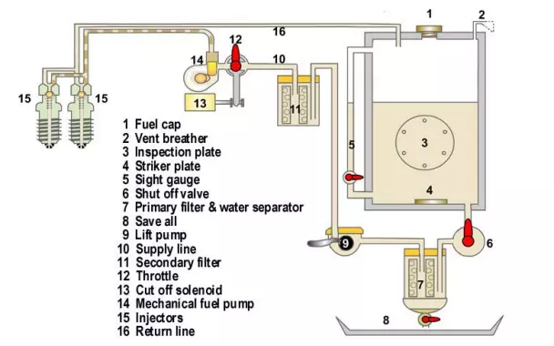
A simple diesel fuel supply system is shown below.
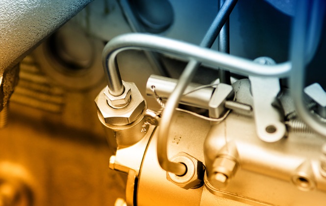
The fuel tank with filler cap and venting breather is measurable by a sight gauge. Fuel is directed to the mechanical fuel pump through the supply line, along which primary and secondary filters ensure clean fuel only reaches the mechanical pump. Additional water separators are often fitted at the primary filter position. A manual lift pump is provided to assist bleeding (priming) the fuel line of trapped air after servicing the fuel filters. The cam driven mechanical pump forces the fuel to the injectors when it is required for combustion.
Other fuel line components include:
Baffle – They are fitted to prevent free surface effect. This affects the stability of the vessel and in extreme cases can cause vessels to capsize.
Drain valve – is fitted to the lowest part of the tank. Its purpose is to drain water or sediment from the tank. A plug or cap is fitted so, if the valve vibrates open, the fuel is not lost or causes a fire risk. Water can be in the tank as a result of:
Coming with the fuel supply;
Condensation due to the level in the tank being kept low for a lengthy period;
Rain or a wave entering through the unsecured deck fittings;
Being mistaken for a water tank.
Emergency fuel shut off – This is fitted to allow the fuel to be shut off outside the engine room in the case of an emergency. It can be fitted anywhere in the metallic fuel line. It cannot be fitted after the flexible fuel line. Where fuel tanks are fitted outside the engine room and the fuel shut offs are easily accessible, emergency shuts offs are not required. An extended spindle can be fitted to the fuel shut off valve so it can be operated from outside the engine room. The fuel shut off and the emergency fuel shut off are then the one valve.
Filling pipe – is fitted to the top of the tank and it is preferable that it be piped continuously to deck level. It does not have to be piped to the deck, if in the event of an overflow; the fuel will not run onto a hot surface and ignite. The end of the pipe is to be fitted with a sealed cap or plug.
Filter/water trap – They can be a combined unit or separate units. The unit provides a secondary means of filtering the fuel from sediment and impurities while the water trap removes any moisture or water. The fuel pump and injectors have very small clearances and any impurities or water in the fuel will cause them to seize. (The fuel acts as a lubricant). In addition, moisture could cause corrosion to those finely machined components. Sometimes additional filters are fitted to the system.
Fuel contents gauge – Several methods are used to measure the amount of fuel. If a sight gauge is fitted the valves must be self closing. To take a reading, open the valves against a spring or lift a weighted handle and, on letting go, it will automatically close. If the glass breaks or the plastic tube perishes, it prevents all the fuel in the tank running into the bilges or in the case of a fire, prevents all the fuel in the tank feeding the fire. If a sounding rod is used, a striking pad must be fitted to the bottom of the tank to prevent damage to the tank through repeated soundings. Modern arrangements now use magnetic flaps to mark the position of a steel ball floating in a sealed levelling pipe. This method resolves leakage and fire risk inherent in the sight gauge.
Fuel pick up – is fitted above the bottom of the tank. This is to allow a safety margin so as to reduce the amount of any water or sediment flowing to the fuel filter. A valve or cock must be fitted directly to the tank.
Fuel return – Excess fuel from the injectors is returned to the tank. It is good practice to operate from one tank at a time and the excess fuel returned to this tank. In this case, the fuel return valve of the tank not being used must be closed. In small vessels it is not practical to operate off one tank as the vessel would develop a list, therefore engines receive their fuel from the port and starboard fuel tanks.
Fuel lift pump – Unless there is a day tank where the fuel is fed by gravity to the engine, it will be necessary to have a fuel lift pump to get the fuel from the tanks to the fuel pump. A fuel lift pump can be a gear, diaphragm or plunger type.
Fuel injector – It is a spring loaded valve located in the cylinder head and allows the fuel, under pressure from the fuel pump, to enter the combustion space. It enters in an atomised form to allow it to mix completely with the hot compressed air so that ignition can take place with efficient combustion. Excess fuel is returned to the tank.
Fuel injection pump – It accurately meters the fuel and delivers it under high pressure at a precise moment to the spray nozzle of the fuel injector.
Inspection opening – is fitted in a position or a number may be fitted to provide access to the whole tank. It allows the tank to be cleaned and inspected.
Vent – the purpose of the vent pipe is to allow the: Escape of air and vapours when the tank is being filled so it is not pressurised; Entry of air as fuel is used so a partial vacuum does not occur; Normal expansion and contraction of the fuel due to temperature change.
It is fitted to the top of the fuel tank at the highest point when the vessel is in normal trim. This is to prevent an air lock developing. An air lock is when the tank is being filled, air or vapours become trapped in the top of the tank, are compressed, and when the pressure exceeds the filling pressure, fuel is forced out of the vent or filling pipes and a spill occurs. The smaller vent pipes terminate in a gooseneck, the end of which must be higher than the filling point.
The end of the vent pipe has an anti-flash wire gauze fitted to it. If the fuel vapours from the vent pipe ignite, the flames cannot penetrate the gauze and ignite the contents in the tank providing the size of the holes in the gauze are not too large.
Before a combustible substance will take fire, its temperature must first be raised to its point of ignition, and, if after it has ignited the temperature is reduced in some way below this point, the flame will be extinguished. A moderate flame can be extinguished by passing a current of air over it, for instance, blowing out a candle. The reason for this is that more air than is required for combustion is supplied to the burning gas, the surplus tending to cool the flame below its point of ignition. In a similar way, gauze, which is a good conductor of heat, prevents the passage of flame, since it loses its heat very rapidly, and the flame upon coming into contact with it, is cooled below the point of ignition; consequently, no flame appears on the other side of the gauze. A good example is placing a lighted match under the gauze. The flame will not penetrate the gauze.
Comments are closed