Petrol fuel systems
Petrol engines use similar tank and supply arrangements to the diesel but dependant on the engine complexity and age may use:
Carburetion, or;
Petrol fuel injection.
Carburettors
Instead of the injector pump and injectors of the diesel engine, the fuel is atomised and mixed with air in a carburettor. The premixed fuel/air is then supplied to the cylinders through an intake manifold. The carburettor regulates the volume of air/fuel supplied to the engine at different speeds and can increase the percentage of petrol in the mix (make it richer) for easier cold starting. This control for this is called a choke.

Carburettors use the venturi principle of locally pressurising air in a narrowing tube. A fuel line (needle valve) opens into this air stream that sucks and atomises the fuel to pre-mix with the air. Carburettors are used in most outboards and small petrol engines. In the last twenty years larger petrol engines with electrical wiring circuitry have been increasingly fitted with electronics fuel injection systems because of their greater efficiency in meeting emissions control regulations. Most carburettors have the following main components:
Float bowl, float and needle valve – keeps a constant petrol level in the float bowl. The fuel pump delivers fuel to the float bowl. As the level in the bowl rises, the float rises on top of the fuel cutting off the flow of fuel into the bowl and forcing the needle valve shut. If the level drops, the float opens the valve and let in more fuel. The float bowl also helps to trap sediment, to prevent it blocking the jets.
Jets – fine brass jets regulate the amount of fuel which is delivered into the air stream drawn through the throat of the carburettor on induction. Several jets may be provided for idle, low speed, high speed, acceleration, etc.
Throttle butterfly valve – positioned in the main throat below the fuel venturi increases or decreases the flow of fuel/air to the engine (throttle).
Choke butterfly valve – positioned above the venturi restricts the flow of air, without reducing the flow of fuel. This chokes the engine for cold starts.
Further information on outboard engine petrol fuel systems is provided in Chapter 8.
Petrol fuel injection
Fuel injection is the modern alternative to the carburetion process that achieves greater control of fuel usage over a variety of throttle settings from idle to full power. This greater efficiency in fuel use meets regulatory standards for emissions controls and reduces fuel consumption.
Rather than being pre-mixed outside of the engine by induced suction in a venturi, a metered quantity of fuel is either injected into the inlet port/s or directly injected into the cylinder by a mechanical or electronic control system.
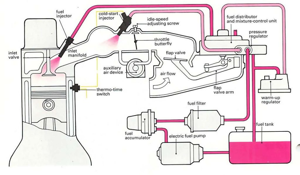
Mechanical fuel injection system (MFI) The air is inducted through an inlet manifold to the inlet ports. A high pressure electric pump pressurises the fuel and passes it through an accumulator (reservoir) to a camshaft driven fuel distributor. This times the injectors to squirt fuel into the inlet port/s air stream during the induction stroke. The quantity of fuel injected is controlled by a throttle linked air intake flap valve that opens with throttle advance creating more piston induced suction. As the piston reaches tdc, the spark plug ignites the mix to initiate the power stroke. Carburettor type choking by restricting air flow to create a richer mix will not work with this system, so an arrangement for additional cold start fuel injection will be incorporated.
Electronic fuel injection system (EFI) The air is inducted through an inlet manifold to the inlet ports. Fuel is injected into the inlet stream of air during the induction stroke and this mix is compressed in the compression stroke. As the piston reaches tdc, the spark plug ignites the mix to initiate the power stroke. The injection point may be positioned at the inlet manifold of all the cylinders (throttle body injection or single point injection), receiving its fuel from a pressurised common rail, or may be separately injected into each cylinders inlet port (multi-point injection).
The components of an EFI single point injection system as shown below include:
Electronic control unit – monitors engine demand and controls component response.
Pump and fuel filter – supplies clean high pressure fuel to the fuel rail and injector.
Fuel rail – a common fuel pipe feeding the injectors.
Pressure regulator – controls pressure in the system.
Throttle body- controls air flow with a valve.
Injector – sprays fuel into the inducted air flow.
Air filter and flow meter –provides clean measured air flow.
Surge chamber – dampens the flow of air.

Direct fuel injection (DFI)
Similar to the injector pump and injectors of the diesel engine, the fuel and air are supplied to the cylinder separately. An injector and a spark plug are fitted to each cylinder head. The air is inducted through an inlet port principally during the induction stroke while the direct fuel injector squirts in a metered spray of petrol that mixes with the air. The mix is compressed in the compression stroke and as the piston reached tdc it is ignited to initiate the power stroke.
The advantage of the system is greater control of the injection moment and richness as may be most efficient for the engine over its operating throttle range. For instance it is most efficient for:
Light load conditions (ultra lean burn) – to inject at the compression stroke.
Moderate load conditions (stoichiometric) – to inject during the induction stroke.
High load conditions (full power) – inject during more during the induction stroke.


Comments are closed