The machinery systems on board ship consist of several safety features for safe and smooth operation of the ship and also for the safety of its personnel. Relief valve is one such important safety device which is used in almost all the machinery systems which deal with extremely high pressures. These high pressures often tend to go over the predetermined limits and the over pressure thus created is the pressure just above the maximum allowable working pressure (MAWP) or designed working pressure.
There are systems onboard a ship which are operated by pneumatics or hydraulics and sometimes even air or electronics. For this reason, the relief valve by construction and operation should be such that even in case of failure of the control system, relief valve must lift to safeguard the system from over pressurized.
How Relief Valve Operates?
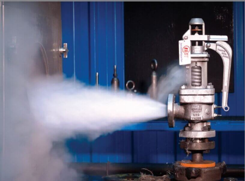
The relief valve operates by thRe action of spring which is determined by an operating pressure. The opening pressure of the spring can be adjusted by an adjusting screw provided on top of the relief valve. The spring acts opposite to the direction of the pressure and thus during normal operation of the machinery, the spring tension will not allow the valve to operate.
When the pressure acting on the valve seat increases to above normal and equalizes with the force of the spring acting downwards, the relief valve will lift and release the excessive pressure until a level of equilibrium is reached.
The lifting pressure of the valve can vary from 8~15% of the working pressure for unfired system, but also depends on manufacturers recommendations. As soon as the pressure of the system becomes normal, the spring which was set to lift at a particular pressure will close the valve as a result of the spring tension and the machinery or system will retain its normal operation.
From safety point of view, valves are constructed to have a full lift to release the excessive pressure when the system is continuously operating in overpressure situation. Such types of valves are called safety valve and relief valve falls in the same category.
Moreover, various safety codes and standards are written for controlling the design and application of the relief valve so that even after failure of other safety systems, relief valve will operate to avoid any catastrophe.
Construction of Relief Valve
The relief valve is a critical part of the safety system which is integrated in the ship’s machinery; hence their designing is kept as simple as possible using materials of compatible strength which can operate in various conditions such as high temperature, air flow, fluid flow, corrosive media etc.
Different parts of relief valve are described below:
Body
The body of the relief valve is normally made up of cast steel. It incorporates all the parts like valve spindle, valve, spring, seat etc. It must be strong enough to withstand the high pressure when valves open to release the excessive pressure through the body.
Inlet & outlet connection
The relief valve inlet is connected to the machinery or system and its outlet connection can be open to atmosphere near to the system only in case of air system, driven through a duct outside the engine room normally for steam system or connected to the inlet or to some reservoir for hydraulic system.
Diaphragm
The diaphragm act as a seal between the inlet outlet connection and valve body so that media should not leak through the valve body when relief valve operates.
Valve seat
The seat must be soft enough so that it should not damage the valve and durable enough for higher operating life else the media for which the valve is used will leak. The seat is normally made of stainless steel coated with soft metal to tackle pressure and corrosion together.
Valve
The valve plays an important role for controlled operation of the relief valve and its malfunction will lead to leakage of media from the machinery or system. It is normally made of stainless steel.
Spindle/ plunger
The spindle/plunger also known as valve stem has a valve attached at the bottom and the spring acts on top of it. The force exerted by spring is transferred to the valve through spindle. The material used for spindle is stainless steel.
Spring and adjusting nut
The helical spring should have proper elasticity strength so that the valve seat can open and close at correct set pressure. Adjusting bolts are located on the top of the body. By rotating the screw the lifting pressure of the valve can be adjusted. The adjusting screw and the spring are generally made of steel alloy.
Choosing a relief valve
To choose a relief valve, variety of parameters has to be studied
Required Relief Pressures
The expected relief pressure is an important factor, which inturn will depend on type of system/ machinery the relief valve is to be fitted.
Fluid Property
The chemical properties of the fluid should be considered before determining the best materials for your application. Each fluid will have its own unique characteristics and may reacts differently with different metal and materials. so care must be taken to select the appropriate body and seal materials that will come in contact with the fluid. The parts of the pressure relief valve which will come in contact with the fluid are termed as the “wetted” components. It is important to select correct valve material and design appropriate piping for a flammable or hazardous nature fluid.
Materials
As discussed in above point, fluid property and application will determine the selection of material for the pressure releif valves. Common pressure relief valve component materials include brass, aluminum and various grades of stainless steel. Springs used inside the relief valve acting as the driving component of the valve are typically made of carbon steel or stainless steel. Brass is also used in common application and it is cheaper. Where thereis a constraint of wight, aluminium can be used depending upon the type of fluid the pressure relief valve will handle. For hazardous and corrosive fluids, stainless steel agrades are popular choice. They also operate well when the operating temperatures is high.
Equally important is the compatibility of the seal material with the fluid and with the operating temperature range.
Flow Rate
Once the relief valve is lifted, how much pressure must be released from the system is determeind by the flow requirements known as flow rate. Piping arrangements, porting configuration and effective orifices are designed based on flow rate requirement.
Size & Weight
In many applications space and weight are limitng factors. For e.g. even a high pressure machinery like air compressor will reuire small size pressure relief valve compare to other machinery having bigger valve with less pressure relief requirement. It is also important to carefully consider the port (thread) sizes, adjustment styles, and mounting options as these will influence size and weight.
Temperature
The materials selected for the pressure relief valve not only need to be compatible with the fluid but also must be able to function properly at the expected operating temperature. The primary concern is whether or not the elastomer chosen will function properly throughout the expected temperature range. Additionally, the operating temperature may affect flow capacity and/or the spring rate in extreme applications.


