Electronic devices have been used in the marine environment for decades and largely consist of navigation or global positioning system (GPS) devices, fish finders, chart plotters, and radar and video displays. Typically these display-based devices range in size from 7-inches to 19-inches, and use buttons or joysticks to make selections or to move within a viewable area. In premium amateur boats and commercial marine vessels, these multiple devices are converging into one large display-based device that performs multiple tasks.
The applications used in the marine environment can include 2D and 3D navigational charts, radar tracking to locate and track bird flocks to help pinpoint schools of fish, a satellite link to view high resolution aerial photographs, and in some instances live video feed for monitoring unmanned areas of the boat. Access to all of this information from one device creates a more enhanced and useful tool and an improved user experience.
The convergence of these applications into a single device requires a common, flexible interface that provides intuitive access for the user. Mechanical and single function buttons will likely become obsolete for these devices as manufacturers increase the displayed content and become more versatile to enhance the user experience.
In addition to the converging device design, the extreme conditions of the marine environment drives device requirements. These environmental conditions can include high ambient and direct sunlight, salt and fresh water spray, environmental condensation, wash down of gauges and electronic equipment to reduce salt water corrosion, elevated operating temperatures, sustained vibration from the engines and heavy jarring from rough waves.
The ideal interface is a touchscreen, but it must be able to withstand all of the aforementioned conditions without negatively impacting the optical clarity of the display. This application brief explains the critical needs of the marine electronics industry and demonstrates how the 3M™ MicroTouch™ System SCT3250EX uses surface capacitive touch technology to achieve those goals.
Critical Application Needs
There are multiple high-level application needs for a touchscreen in the marine electronics market. They are:
· Optical Clarity
· Sealability
· Product Robustness
· Touch Accuracy
· Integrated Touchscreen Solution
· Worldwide support
Optical Clarity
Optical clarity is a broad category and contains several focus areas:
· Light transmission
· Anti-glare treatment
· Color
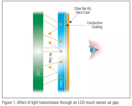
Light transmission is the percentage of light that passes from a light source (like an LCD) through a touchscreen overlay and is registered by the user’s eye. This transmission can be affected by optical coatings that may be placed on the touchscreen to provide touch functionality or to control device or environmental effects, such as LCD noise emission. Transmission can also be affected by the existence of an air gap between the front surface of the LCD and the touchscreen overlay. The air gap provides a medium in which the light scatters, reflecting back and forth between the LCD and back surface of the touchscreen. This reduces the amount of light traveling to the user’s eye making the display appear dim or dark [FIGURE 1]. Optical bonding of the touchscreen to the LCD (eliminating the air gap) can minimize light reflection and results in brighter colors and enhanced color contrast.
Anti-glare is a surface modification treatment, such as chemical etching, that is applied to the front surface of the touchscreen to reduce glare from sunlight or other external light sources. A touchscreen that lacks any anti-glare treatment will give the viewer the experience of a glossy-finished photograph. This type of finish is very shiny and
finger prints are easily seen on the surface. An anti-glare treatment is the equivalent of a matte-finished photograph. The clarity of the picture is slightly reduced when compared to the glossy finished photograph. However, finger prints are not as easily seen and the shininess is gone, making it easier to see the displayed image under a wider range of light settings. There are varying degrees of anti-glare treatment. As the anti-glare characteristic increases the clarity and transmission will decrease [FIGURE 2]. The anti-glare treatment must be optimized to achieve satisfactory clarity and transmission.
Color is a third aspect of optical clarity. There are three color coordinates that affect color and how it is perceived by the human eye. They are L*, a*, and b*. In 1976, the Commission Internationale d’Eclairage (CIE) recommended a color scale where they defined color space in a cube format with L*, a*, and b* as dimensions in space within the cube. This cube format as defined by CIE is known as CIELAB [FIGURE 3]. The purpose of the scale is to provide an approximate uniform color scale. As shown, the L* axis runs from top to bottom and represents a color shift from white to black respectively. The a* and b* axes are orthogonal to each other. Movement along the axes in a particular direction defines the color correction needed to bring the sample back to true color. Color can be negatively affected by variables like ultra violet (UV) light, optical coatings, anti-glare treatments and any adhesives used to bond the system together. The result from the aforementioned possibilities can result in a color shift that can have a negative impact on the user’s perception of color.