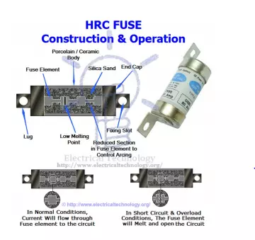
This type of fuse contains a fuse wire in it, which carries the short circuit current safely for a given time period. During this period, if fault is removed, then it does not blow off otherwise it will melt and remove the circuit from electrical supply hence, the circuit remains safe.
The common material, which is used to make an HRC fuse is glass, but this is not always the case. Other chemical compounds are also used in HRC fuse manufacturing and construction based on different factors. Its external enclosure is made fully airtight in order to avoid the effect of atmosphere on the fuse materials. The major objection on HRC fuse is low and uncertain breaking capacity of semi enclosed fuse.
The fuse inside is filled with silica based powder, which helps in quenching the arc produced during fusing. Ceramic will help in isolating the fuse from outside atmosphere.
Application of H.R.C fuses:
· Used for protection of Transformers, Motors and automobile, etc.
· It is also used in motor stators
· Backup protection
Surge limit of a turbocharger
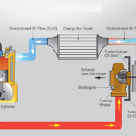
Surging in a turbocharge happens when a reversal of gas flow through the turbo charger compressor happens. When an engine cannot use up all the air delivered by the turbo compressor, the pressure inside the scavenge receiver increases rapidly. This air will be blown back through the turbo compressor through the diffuser ring. It can cause imbalance of the rotor shaft and vibrations in the system which is not at all good for the plant.
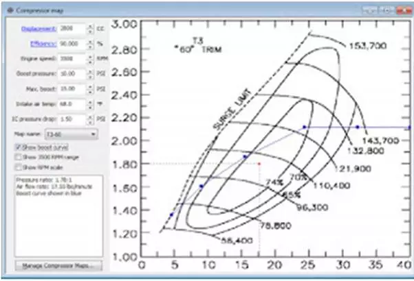
Turbocharger characteristic curve is a plot between pressure ratio and air flow through the turbo compressor. This curve is defined for each RPM of the turbocharger and shows how the turbocharger will behave under such RPMs. Turbocharger will have different efficiencies under different pressure ratios for same RPM.
As the efficiency of the turbocharger increases for the same RPM, the turbocharger reaches more and more near to the surge point. Surge point is a particular pressure ratio at which a turbocharger will surge under a particular RPM. let’s say a T/C starts surging at a pressure ratio of 2.0 for an RPM of 15000. The surge point for 15000 RPM can be said as 2.0 bar under this condition. Above 2.0 pressure ratios, the T/C mass is definitely going to surge, be it 2.1 or 200 for 15000 RPM.
If u draw a line connecting all the pressure ratios or surge points for all the T/C RPMs possible, u get what u call the SURGE LINE .See the image below for more clarity.