working principles and operational guideline
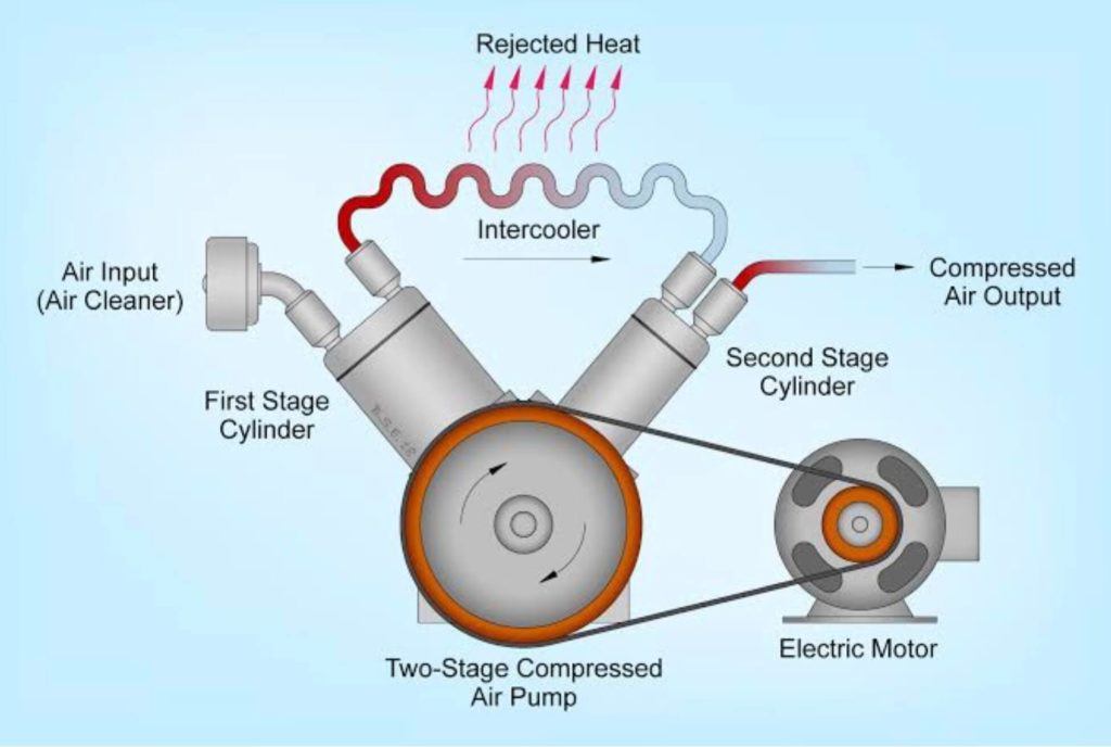
· Use of compressed air for ships machinery Compressed air has many uses on board ship, ranging from diesel engine starting to the cleaning of machinery during maintenance. The air pressures of 25 bar or more are usually provided in multi-stage machines. Here the air is compressed in the first stage, cooled and compressed to a higher pressure in the next stage, and so on. The two-stage crank machine is probably the most common. Air is drawn in on the suction stroke through the first-stage suction valve via the silencer/filter. The suction valve closes on the piston upstroke and the air is compressed. The compressed air, having reached its first-stage pressure, passes through the delivery valve to the first-stage cooler. The second-stage suction and compression now take place in a similar manner, achieving a much higher pressure in the smaller, second-stage cylinder.
· After passing through the second-stage delivery valve, the air is again cooled and delivered to the storage system. The machine has a rigid crankcase which provides support for the three crankshaft bearings. The cylinder block is located above and replaceable liners are fitted in the cylinder block. The running gear consists of pistons, connecting rods and the one-piece, two-throw crankshaft.

· The first-stage cylinder head is located on the cylinder block and the second-stage cylinder head is mounted on the first: each of the heads carries its suction and delivery valves. A chain-driven rotary-gear pump provides lubricating oil to the main bearings and through internally drilled passages in the crankshaft to both connecting rod bearings. Cooling water is supplied either from an integral pump or the machinery space system. The water passes into the cylinder block which contains both stage coolers and then into the first and second stage cylinder heads. A water jacket safety valve prevents a build-up of pressure should a cooler tube burst and compressed air escape. Relief valves are fitted to the first and second-stage air outlets and are designed to lift at 10% excess pressure. A fusible plug is fitted after the secondstage cooler to limit delivered air temperature and thus protect the compressed-air reservoirs and pipework. Cooler drain valves are fitted to compressors. When these are open the machine is ‘unloaded’ and does not produce compressed air. A compressor when started must always be in the unloaded condition. This reduces the starting torque for the machine and clears out any accumulated moisture in the system. This moisture can affect lubrication and may produce oil/water emulsions which line the air pipelines and could lead to fires or explosions.
· To stop the compressor, the first and second-stage cooler drain valves should be opened and the machine run unloaded for two to three minutes. This unloaded running will clear the coolers of condensate. The compressor can now be stopped and the drains should be left open. The cooling water should be isolated if the machine is to be stopped for a long period. Automatic compressor operation is quite usual and involves certain additional equipment. An unloader must be fitted to ensure the machine starts unloaded, and once running at speed will load’ and begin to produce compressed air. Various methods of unloading can be used but marine designs favour either depressors which hold the suction valve plates on their seats or a bypass which discharges to suction. Automatic drains must also be fitted to ensure the removal of moisture from the stage coolers. A non-return valve is usually fitted as close as possible to the discharge valve on a compressor to prevent return air flow: it is an essential fitting where unloaders are used.