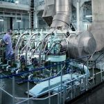
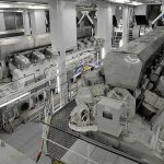
This article describes the auxiliaries mandatory to the efficient running of a steam turbine ship and their location.
Marine Turbine Auxiliaries
I have laid out the marine steam ship engineroom as I remember it when I was an engineer at sea. The turbines in the steam ships in operation were replaced by marine diesel main engines just after this, so I doubt things haven’t changed much. However there has been a recent innovation whereby the steam turbine has been resurrected, the steam being raised by other means than fossil fuelled boilers. The engine room layout of these types ships may well be different, but the same steam supply and exhaust principles will apply.
I have drawn the auxiliaries in their approximate locations and have numbered them in the sketch, please read these descriptions along with the sketch
Deaerater
Located at the top of the engineroom, this is a vertical, cylindrical steel pressure vessel into which the condensate from the condenser hot-well is pumped. The condensate is sprayed into the vessel over heated coils and the oxygen and any other gasses are expelled. It removes the gasses from the condensate to prevent them entering the boiler feed system, where they would corrode the internal surfaces of the boiler water tubes.
Lube oil header tank
This tank feeds the lube oil system by gravity. It is supplied by the lube oil pump, drawing the oil from the lube oil tank located under the bottom plates. This tank can either supply the whole system or just be used for emergency feed in the event of a blackout or loss of a lube oil pump, in which case it will supply the main turbine bearings with oil until the turbine stops rotating.
Control platform
Here the main controls for the turbine are located; Ahead, Astern and Guardian steam valves, boiler oil burners controls normally used to control steam pressure when maneuvering. On the control panel itself are the usual selection of pressure and temperature gauges, with the two most prominent being the engine rev-counter and the condenser vacuum gauge.
Air ejectors
These are used to produce a vacuum in the condenser by ejecting the air by feeding high pressure steam through a venturi type device; the steam exhausts to an auxiliary condenser.
Double reduction gearbox
Both the HP and LP turbine output shafts are coupled to the gearbox. This reduces the revolutions from several thousand to the output speed of the propeller shaft normally about 100 RPM. The gearbox bearings and gears are spray lubricated separately from a pump run off the turbine. The oil returns to the main tank with any metal particles being picked up by the magnetic lube oil filters.
Thrust block.
The thrust block is located where the main propeller drive exits the gearbox and transfers the propeller thrust through the hold down bolts into the ships plates.
Propeller shaft bearings
Also known as tunnel bearings, these are white metal bearings that take the load of the prop shaft ensuring even running. They are lubricated by ring feed, i.e. the bottom of the ring is immersed in the oil bath and rotates with the shaft thus transferring the oil from the ring to the bearing.
Stern gland
The stern gland prevents ingress of seawater to the shaft tunnel. It is packed in a particular manner whereby the packing strips (oil and graphite impregnated) are cut to fit precisely around the shaft and between the shaft and the stuffing box. The packing strips are mitered at 45° at the ends inserted to the stuffing box using a hammer and a dog-leg piece of wood and staggering the ends as per the clock i.e. 3, 6, 9 and 12.
Once the gland is fully packed, the gland ring is refitted over the studs and again tightened as per clock. It is always best when stripping out an old gland to use a special tool resembling a large corkscrew and to count the number of packing strips removed, so you know how many are required to repack it.
Lube oil cooler
The lube oil pump circulates the oil around the various components, then through the lube oil cooler that is used to cool the oil, helping to keep the lubricated components cool. It is supplied with seawater from the shipside valve which is pumped through the cooler by the lube oil seawater circulating pump.
Main condenser and hotwell
Probably the most important of the auxiliaries, it draws the steam by vacuum from the last few stages of the LP turbine and condenses this to condensate that passes onto the hotwell. Both the condenser and the hotwell are located under the bottom plates.

This pump draws the condensate from the hotwell and discharges it to the deaerater tank. The gas-free condensate then drops from the DA to the condensate feed tank under the bottom plates.
Usually steam driven, this pump draws condensate from the condensate tank and discharges the condensate at high pressure through the economizer where hot exhaust gasses from boiler heat the condensate. This condensate then enters the boiler water drum via a feed regulating valve (which controls the water level in the water drum).
The centrifuge system is located just above the lube oil tank, from which it draws the lube oil through a heater. The oil is purified by centrifugal motion and any water or impurities expelled and the purified oil being returned to the lube oil tank. The centrifuge is normally on line permanently, except when being cleaned, when the standby one takes over.
There are two sets of these, one on the suction side of the lube oil pump and one on the discharge. The suction filters are really a set of magnetic screens, which pick up any bits of ferrous metal in the oil. The discharge set are duplex filters, also magnetic and a strict maintenance procedure is required to keep both sets clean and working efficiently
In the gravity supply system, the pump draws the oil from the lube oil tank through a set of screens and discharges the oil through the lube oil cooler to the header tank. In a pressurized system the oil follows the same route, supplying the main turbines and gearbox, there being an orifice plate in the discharge line which bleeds of oil up to the header tank.
This supplies seawater from the shipside valve to the main and auxiliary condensers.
These are used to produce distilled water from seawater. This distilled water is stored in tanks and is used for boiler feed make-up. The evaporator consists of a vessel which is under a vacuum and is filled with seawater covering a set of coils. High pressure de-superheated steam passes through the coils causing the seawater to boil and evaporate to steam. This steam then rises into an integral condenser where it condenses to distilled water. This is pumped to the distilled water tanks. Periodic cleaning of salt from the outside of the steam coils is essential to maintain the efficiency of the evaporator.
This is actually the main engine sump into which the lubricating oil drains. It is pumped from here to the header tank through a series of filters and a cooler.
This tank contains the condensate returned from the DA and the feed pump draws the condensate from here
The exhaust gases from the boiler furnaces heat the condensate before entering the boiler water drum.
Note. The ships boilers including blowdown valves, boiler water treatment, oil pump and burners, soot blowers and forced draught fans will be covered in the next article.


Comments are closed