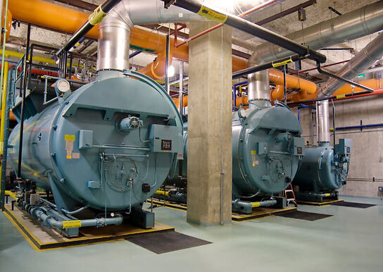
Boilers of all types are subjected to extremely hazardous conditions involving very high temperatures, abrasive, and chemically aggressive fuel constituents. Vigilance is essential at all times and the prime consideration is cleanliness of both the gas side and furnace.
Introduction:
The boiler furnace is the place where the combustion of fuel takes place and it is covered by refractory materials which prevent the heat loss due to radiation. A high efficiency is obtained when heat losses are low. A major heat loss occurs if the furnace refractory material is not maintained.
For any boiler inspection, the inspector must plan out a route for his movement starting from the furnace.
1. Almost always, the inspector must start at the furnace. The reason being that the furnace reveals the quality of combustion and its effect s and any distortion at the crown or the tube walls signifying the problems originating at the water side. In fact a good clean furnace with no signs of distortion could assure the inspector that the boiler is in good running condition.
2. The next in succession should be burner unit, the bottom headers, and the boiler bottom.
3. Mounting attachments on the upper shell will follow before entry is made through the manhole to inspect the water side of the steam space.
4. Top mountings will be checked before entering the gas space through the inspection door for look at the boiler tubes.
5. The inspector will end with a check on dismantled mounting parts arranged in order for the purpose.
6. If in doubt of gas side corrosion, checks on the gas uptake could be done as a final step in the inspection route.
Boiler Furnace


Sludge deposits continue to be the prime cause of non-operation of internal controls and overheating of a furnace in a vertical boiler.
Overheating distortion on the furnace crown is mainly due to a deposit of oil, scale, or sludge on the heating surface or due to water shortage. The lower section of the crown causes overheating distortion due to the sludge deposits.
The furnace connecting to the shell may have welding cracks due to rapid fluctuation of thermal and mechanical stress, the results of improper starting up or shutting down procedures.
Direct flame impingement resulting in deformation of the crown or a local bulge in wall tubes opposite the burner opening is also possible.
Dry cracks in the furnace mouth, crown, or the furnace tubes caused by flame impingement are possible due to scale encrustation at the water side and forcing of the boiler. Areas suffering from poor circulation or relatively uncooled area are also susceptible to the above failure.
Deep cracks in the furnace mouth, crown, or furnace tubes caused by flame impingement are possible due to scale encrustation at the water side and forcing of boiler. Areas suffering from poor circulation or relatively uncooled areas are also susceptible to the above failure.
Deep cracks on plating should be stopped by drilling a hole at each end, opening up, and then welding.
Indifferent feed water may cause pitting of the furnace crown. A careful examination through the bottom manhole door would require detecting the above grooving.
Brickwork protecting the foundation, if damaged, may cause distortion of the bottom plating underneath the furnace. Damaged brick wok need to be removed to inspect the bottom plating for distortion before repair s to the brick work is carried out.
Corrosion: Any sign of corrosion on plating should be chipped clean and brushed clear. It is also possible to build up the weakened areas by means of electric welding. Pitting arear are difficult to protect from further corrosion due to the difficulty in maintaining the protective magnetic oxide layer
Boiler Furnace Defects


Remedies for Common Defects:
Furnace crowns that have suffered a gradual deformation can be jacked back to their original shape with or without heat. A shaper deformation may require the plating to be slotted so that the clean metal can extrude into the gap during heating and jacking. The slot is butt welded on completion. A much neater repair is to burn out the affected area and replace with a butt-welded insert section cut from a scavenged furnace. For a severely damaged furnace with a pronounced large belly, replacement could be the only answer.
Furnace tubes must be inspected for correct alignment and the tubes together must form a circular tube wall; anywhere the tubes are deformed, the furnace shape will show up as misaligned. Distortion to a very small extent could be accepted, but beyond that renewal of tube will be mandatory.
Furnace tubes, if damaged (cracked, holed, or deformed) need to be renewed with new tubes. Only under emergency conditions could one be allowed to operate a boiler at low load with plugged furnace tubes. (Plugging could be carried out with tapered steel plugs on each tube ends.)
The bottom plug will have to be inserted through the bottom header. The difficulty in doing that may also compel cutting windows on tubes from the furnace end and manipulating the tapered plug in position.
Furnace Inspection:
REFRACTORY MATERIALS:
1. The front wall with its quarls receives full radiant heat and also deteriorates more rapidly and may cause spalling of brickwork, misshapen quarls, and badly burnt air registers.
2. Refractory to protect the front part of the water drum, particularly below the screen tubes, may fail and expose the drum to the direct heat of the furnace resulting in circumferential thermal cracking.
WATER WALL TUBES:
1. There is a greater possibility of overheating due to restriction in circulation.
2. Roof tubes having horizontal portion show effect of overheating due to water shortage very quickly. Roof tubes with roof fired boilers are also prone to distortion due to overheat.
3. Tubes around soot blower openings have greater chances of overheating due to turbulence at the bends restricting circulation.
SCREENING TUBES:
1. Check for direction due to overheating maximum permissible deviation or sag may be 2 inch in 12 ft before renewal.
2. Leakage at top expansion usually shows by white stains down the outside of tubes- these may be re-expanded.
3. Check gas passage through superheated banks for cleanliness.
4. Examine furnace end of superheater supports visible through screen tubes.
5. Gas baffle conditions above and below the superheater attached to the rear screen tubes to verify which may cause gas short circuit giving local overheating in superheater and loss of superheat.
6. Screen tubes exposed to excessive heat due to flame impingement, forcing, etc. possible high temperature creep cracks or circumferential fatigue fracture due to rapid thermal cycling.


Comments are closed