
The article discusses expressions that are generally useful for determining the various factors involved with fluid flow through nozzles and orifices. The practical relevance is also demonstrated through an experiment.
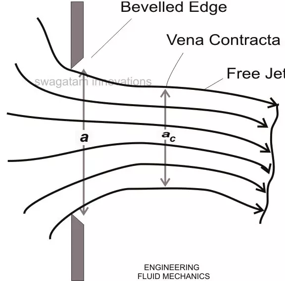
Consider a jet of fluid forcing out from an orifice with area a. Here, the contracting tendency of the flow forms a vena contracta of area ac under an atmospheric pressure above which the jet of fluid tends to expand. However this expansion may depend on the resistance offered by the entrained surrounding fluid.
Also, here the passage streamlines are significantly parallel with each other. Though the expanding tendency of a water jet in air may be significantly high, it’s just visible with an air jet in air or a water jet in water.
The coefficient of contaction can be given as,
C = ac/a
At the vena contracta, the actual velocity uc is less than the theoretical velocity u.
Therefore, the coefficient of Velocity Cv = uc/u,
Another factor called the coefficient of discharge carries a ratio of the actual discharge ac.uc to the theoretical discharge a.u, and is given as,
Cd = ac.uc/a.u = Cc × Cv——————————————————————–(1)
Taking the velocity uniformity as the prime factor, orifices may be classified into many different sizes and shapes.
All varieties of mouthpieces, whether straight or converging-diverging types, all fundamentally have an increasing effect of Cd, through a relevant increase of Cv, when run fully and allowing limited jet contractions.
Mouthpieces and orifices are primarily designed with a view of releasing a flow and emptying a container. The time taken for emptying the container can be evaluated by considering an elementary fluid strip inside the container and identifying for time δt to discharge it.
Considering the arbitrary sharp container (see figure), let an instantaneous level of the fluid be at a height h over the orifice. Assuming δh to be a fall in the height of the level and δt, the time taken for it, the volume of liquid discharged for this period of time can be given as:
δ V = a δh, where a = the relevant area of cross section.
The velocity through which the container evacuates is given as:
Uc = Cv √2gh
The flow area of the fluid at the vena contracta is given as:
Ac = Cc a
Finally, the discharge through the orifice can be written as:
Q = Cd a√2gh
From equation (1) we see Cd = ac.uc/a.u = Cc × Cv, also the volume of liquid escaping from the orifice in time δt should be
δ V = Q δh
Taking δ V and Q into account and also understanding the fact that the discharge time is inversely proportional to the instantaneous height of the fluid, we write,
δt = -A δh/Cd a √2gh,
Integrating the above equation gives,
T = 0ʃT dt = – H1ʃH2 A dh/ Cd a √2gh
= -√2gh / Cd a H1ʃH2 A h-1/2 dh
The above expression gives us the time taken for emptying the fluid from a height H1 to H2.
Calculating the flow through orifice and nozzle, through a practical experiment:
Nozzles and orifices in tanks and conduits are basically used for discharging the air or fluid content enclosed in the tank into the outer atmosphere. The conditions sometimes make it imperative to find the discharge rate or parameters like time rate required for emptying the particular tank through its relevant nozzle.
The following experiment can be done for practically learning the above relations:
Procedure:
Make a circular orifice with a sharp edge connected to the side wall of an empty tank. Note the diameter of the orifice as D.
Determine the position of the overflow pipe so that maximum height and start flow can be achieved (approximately).
Optimize the rate of the flow of the fluid so as to maintain a constant head H in the tank.
The flow rate now may be measured either using a volumetric or gravimetric method, the later being more accurate with smaller flow rates.
Next, find the x and z coordinates of the flow angle, issuing out of the device, up to the point where the jet just starts disintegrating.
For the calculation of the emptying time, determine the relevant time interval T = (t2 – t1) using a stop watch for a corresponding fall in the height ΔH = H1 – H2.
Repeat the procedure using a nozzle fixed over the circular orifice on the side wall of the tank.
Result:
From the gathered data, tabulate:
The flow rate Q through volumetric or gravimetric methods as discussed above.
The mean z coordinates corresponding to the measured x coordinates, and evaluates the theoretical magnitude of the z coordinate using the relation:
z = -x2/4H, and Cd = Q/a.√2gH
where a is the area of the orifice
The coefficient of contraction Cc, which may be given as the ratio the vena contracta area and the area of the orifice.
Calculate:
The ratio of the discharge coefiicient of the nozzle to the orifice, for the highest inlet head, given by λ.
The ratio of time taken for emptying of the fluid by level ΔH through the nozzle and through the orifice, relate them with λ as acquired from the above step.
A graph of log Q vs log H may now be plotted for observations and inference.
