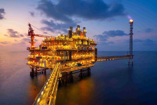
There are numerous types of offshore oil and gas production platforms which can either sit or be fixed on the seabed or float, but the processing of the hydrocarbons is the same. The fluids and gasses are separated into different process chains before being exported ashore via subsea pipeline.
The late 60’s saw the start of the offshore construction industry in Scotland. There were quite a few yards then, Highlands Fabricators and McDermott’s in the North, Howard Doris’s yard at Kishorn in the West coast where mostly concrete platforms were fabricated and Lewis Offshore on the Isle of Lewis. There were also a scattering of yards in the Clyde area and Harland & Wolff of Belfast built the Sea Quest which discovered the first oil in the North Sea. It was built while I was serving my time as a marine fitter in the at H & W yard in the 1960’s. All the yards had access to deep water berths for loading the structures onto barges, launching facilities or drydocks.
The following sections examine the construction of a steel jacket fixed production platform. This is the most common and very suitable to North Sea oil and gas fields on the continental shelf. We shall also have a look at how the offshore production platforms work; oil and gas is processed on the platform before being exported ashore via the subsea pipelines.
Types of Offshore Production Platforms
There are various types of offshore oil and gas platforms
· Steel Jacket Fixed Platform
· Tension Leg Platform
· Concrete gravity base Platform
· FPSO – Floating Production, Storage Offloader
From the above we shall examine the steel jacket fixed platform in the following sections.
Construction and Installation of Offshore Oil and gas Production Platform
The platform consists of two parts the jacket and the deck. A four legged jacket is fabricated from large rolled steel circular steel sections, welded together and interdispersed with smaller tubular members welded to the main legs using prefabricated nodes. This gives the structure its strength as it tapers from the wide bottom sections to the top smaller section.
The deck or topsides contain the hydrocarbons processing equipment are fabricated in square or rectangular pallets which are welded together and plated over. There are usually three or four different deck levels and these contain all the equipment required to run the various process trains.
Construction of the Jacket
The jacket is normally built on its side although I have seen small ones built vertically.
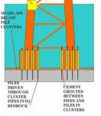
At the bottom of the legs are the pile clusters and mud flaps. The pile clusters are a circular ring of pipes welded to the legs. These are the means of attaching the jacket to the seabed permanently by having long steel piles hammered through them into the seabed, effectively nailing the structure to the bedrock. The mud flaps rests on the bottom of the mud.
Floatation tanks may be attached to the jacket which as well as the hollow legs, facilitate the ballasting of the Jacket at installation.
Installation of the Jacket
Once completed the structure is skidded onto a barge and towed to the location where it is slid off the barge and settles in the water coming gradually to the vertical position over the capped reservoir well, sinking as it is slowly de-ballasted. Once in the right position the piles are driven through the pile sleeves and mud flaps by a pile driver on a barge. Cement then is poured into the gap between the piles and the pile sleeves acting as an efficient grout and effectively securing the whole structure to the seabed.
A sketch of a steel jacket attached to the seabed is shown below
Fabrication of the Deck
The deck is fabricated from a variety of steel sections, RSJ’s, I beams and special pre-fabricated sections.
These are made into rectangular pallets and welded together then plated over to form the decks. During construction of the deck the production equipment is installed on the various decks. This has to be done in sequence as a lot of the electrical/ mechanical equipment and interconnecting pipework and HVAC is integral to the structure as different rooms and modules and compartments are fabricated.
Once all the structural work is completed and the equipment installed, onshore commissioning can commence. This involves testing every electrical cable, hydrotesting the pipework, leak testing the HVAC system, running up motors, pumps and generation power units.
Installation of the Deck
The deck is then put onto a barge and towed out to the jacket location. A heavy lift barge crane swings the deck over the jacket and both are welded together with great accuracy, a couple of mm between the mating faces being the norm.
The offshore commissioning activities are carried out and eventually the final pipe in the reservoir perforated by small explosive charges. This allows the orderly high pressure flow of gas and fluids to come up the riser to the production manifolds.
Production Platform Oil & Gas Processing
The production platform is installed over the wellhead and risers connected to the platform production manifolds.
A mixture of gas, oil an water are forced up the risers from the reservoir into the high pressure (HP) and low pressure (LP) production manifolds. From the HP manifold the gas is directed to the HP Separator a thick walled vertical pressure vessel, where due to pressure difference the gas flashes off. From the LP manifold the low pressure gas, water and oil is directed to the LP Separator, another vertical pressure vessel where the oil is directed to heaters, water is separated out and sent to produced water system and any gas compressed and set to join the HP separator gas outlet.
Gas Processing System
The wet gas leaves the HP separator and along with compressed gas from the LP separator recovered gas flows to gas compressors. These are normally gas turbine driven and compress the gas before discharging it through dehydration process in the glycol contactor, the glycol removing any water particles in the gas. Some of this gas known as fuel gas is diverted to the knockout drum where liquid condensates are removed. It is the further filtered and heated for use on the platform power generation gas turbines, export pumps and compressor turbines.
The remaining gas is now ready to be sent ashore by the gas export compressors through the subsea pipeline.
Oil Processing System
Once the oil leaves the LP separator it is pumped by the oil booster pumps through an oil heater then into a coalescer, from where it can be further processed or sent ashore by the main on line pumps by subsea pipeline.
Produced Water Treatment
The water from the LP separator is pumped through sand filters and cyclones then an oily water separator to remove the solids and oil. From here the water will be passed through a degasser drum where any remaining oil and gas is removed. This gas residue is then put to the flare where it is flared off to atmosphere, the oily water being returned to the LP separator.
The produced water is continually monitored and pumped overboard unless it is needed for injection back down into the reservoir, an enhanced oil recovery method to increase production.
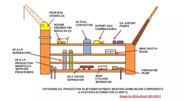
A sketch of an offshore production platform is shown below; please note I have only shown some of the major equipment, relocating some of these to aid clarity. I have also omitted the lifeboats and survival gear. The accommodation on modern platforms is usually located on a separate steel jacket nearby, following the Piper Alpha Disaster.
Comments are closed