It is very important in a large two stroke slow speed engine to transfer the power generated in the combustion chamber to the crankshaft without transmitting transverse forces to the piston and large thrust directly to the crankshaft. Hence an arrangement is provided to compensate this which is known as Crosshead.
The reciprocating action of piston is converted into rotary motion for crankshaft by means of the cross head where the piston rod and connecting rod are attached on both sides.
A routine maintenance has to be performed on crosshead bearing as per maker’s instruction. Following procedure is to be followed when carrying out crosshead bearing removal of a MAN MC-C engine:
1. Inform company and take permission.
2. Take immobilization certificate from port.
3. Read the manual and have a toll box meeting with everyone involved in the job. Discuss the procedure.
4. Prepare important tools and spares to be used in this operation
5. A risk assessment of all personnel doing the operation to be prepared and documented
6. Shut main engine starting air
7. Engage turning gear to the main engine crankshaft
8. Open indicator cocks of all cylinders
9. Stop main engine lube oil pump after cooling down of engine
10. Open crank case doors of fore and aft unit
11. Open crank case doors of that unit in which maintenance is to be carried out.
12. Put blower and ventilate the crankcase thoroughly as it is an enclosed space.
13. Prepare enclosed space entry checklist.
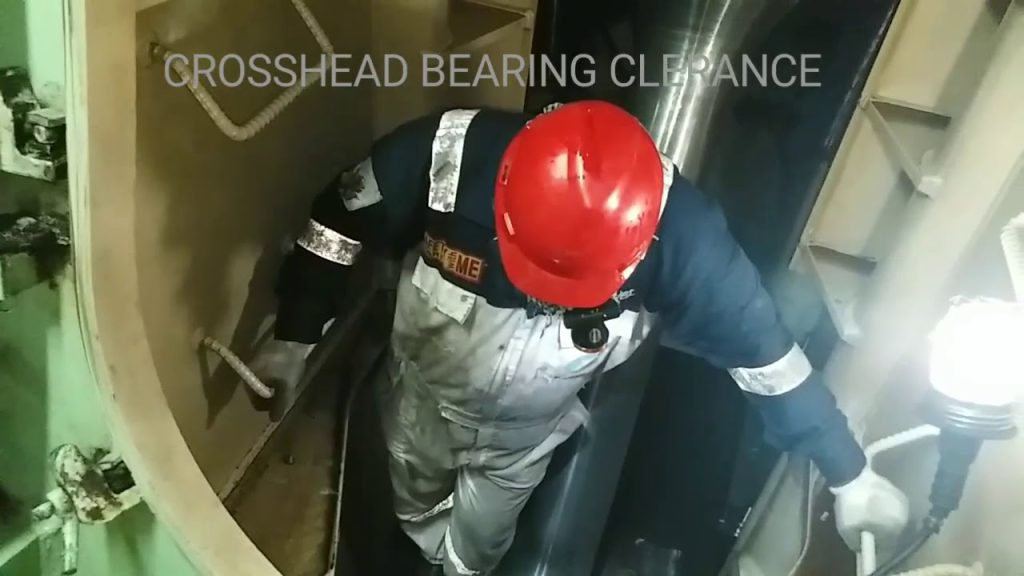
14. After sufficient ventilation wearing proper PPE you can enter the C/C.
15. Turn the crank throw to 90° before BDC.
16. Check the bearing clearance by inserting feeler gauge b/w bearing cap and crosshead journal exactly next to the landing surface of the piston rod foot.

17) The wear limit for a cross head bearing shell is limited to 50% reduction of the oil wedge length (L).[ L=10mm]
18) Turn the crankshaft down enough to give access to nuts and screws on piston rod.
19) Mount two chain blocks on the top of the crankcase for suspending the piston rod.
20) Loosen and remove the locking wire and screws on the piston rod foot.

21) Mount the lifting eye bolt on each side of the piston rod foot.
22) Turn the crosshead to TDC.
23) Hook the chain blocks to the eye bolt on the piston rod foot. And turn the crosshead down so that piston is now suspended on the chain blocks.
24) Turn to BDC.
25) Mount the hydraulic jack on the crosshead bearing cap nut and loosen them. [pressure : 1500-1650 bars]
26) Mount the lifting attachment on the head of the connecting rod.
27) Suspend the two chain blocks from the lifting brackets in the athwart ship direction.

28) Mount the 2 eye bolts on the top of the cross head bearing cap.
29) With the help of the two chain blocks lift the bearing cap. Take it out of the engine and place it on a wooden base.
30) To check the upper bearing shell, remove the locking screws and push the shell out.
31) Mount the chain blocks to the lifting brackets on the frame box wall.

32) Turn the crosshead up until the piston rod lands on the crosshead. Ensure that the guide ring in the crosshead fits correctly in the centre hole of the piston rod.
33) Do not remove the chain blocks or the lifting eye bolts.
34) Turn the crosshead to TDC and attach the chain blocks to the lifting arrangement and haul it tight.
35) Mount the four supports for the guide shoes on the crosshead guide.
36) Carefully and slowly turn the crankshaft towards to exhaust side and make sure the crosshead guide sits on the supports.
37) Turn the crank throw towards BDC slowly while following with the chain blocks, thus continuously supporting the connecting rod.


38) In case it is necessary to remove the lower bearing shell, tilt the connecting rod towards the door on the cam shaft side with means of chain blocks.
39) Dismount the locking screws and turn the bearing shell so far up that an eye bolt can be mounted. Lift the bearing shell out.


