The dynamic behavior of piles under lateral loading has received much attention in recent years due to its application in machinery foundations and structures exposed to dynamic loads such as wind and earthquakes. However, the dynamic behavior of piles and pile groups is far from being completely understood, as the soil-pile and the pile-soil-pile interactions are very complex phenomena especially in the case of near-shore and offshore structures. Structures that are usually founded on single pile or pile groups (such as offshore and near-shore platforms, wind turbines, docks, jetties, wharfs, mooring structures, and bridge piers) might become subjected to significant dynamic effects due to wave loads, wind actions, mooring and impact forces from ships, as well as earthquake motions. When subjected to dynamic load, the behavior of the soil-foundation system depends on the characteristics of the surrounding soil, the configuration of the foundation, the inertia of the superstructure, and the nature of the dynamic excitation. In particular, the stiffness and damping characteristics of a soil-water-pile system (impedance function) exhibited during an earthquake motion or any dynamic action on superstructures founded on piles depend on the mechanical and geometric properties of the soil, pile, and their mutual interaction and must be included in the structural model if accurate predictions are desired. In this sense, the estimation of soil-water-pile system stiffness and damping is a key step not only in the project phases, when a variety of different foundation configurations should be compared and a choice on the basis of the structure’s functional requirements should be done, but also in the structural modeling and in the verification procedures. For both research and design purposes, the soil-foundation interaction may be approached with a direct method, modeling the whole dynamic soil-pile system with numerical methods or using theoretical approaches, i.e. distinct methods to evaluate kinematical and inertial effects, with different degrees of refinement.
It is worth pointing out that the results of these methods are very sensitive to many parameters that define the dynamic characteristics of the soil-pile system. Experimental results carried out on full- or small-scale in situ and laboratory tests are essential for the accurate calibration and validation of these models. Over the past decade, the understanding of dynamic interaction between pile foundations and the surrounding soil has advanced significantly and a large number of theoretical studies have been published following the numerical and analytical approaches. In the field of experimental tests, a variety of small-scale model tests have been performed to improve the understanding of the effects of soil and pile parameters on the system response. On the contrary, very few dynamic tests with lateral excitation on full-scale piles in field conditions (and even less on near-shore/offshore piles [1, 2]) have been reported in the literature. Full-scale dynamic pile response tests are essential as a point of reference with which to compare results of scale-model tests and numerical analyses. In situ tests have the advantage of providing “real” soil and pile stress conditions, whereas laboratory tests offer the opportunity of performing parametric studies under known soil conditions; obviously, taken together, field and laboratory tests assure an accurate and adequate knowledge completing each other.It is worth noting that, since a seismic soil motion cannot be reproduced in field tests, theoretical methods for seismic analysis cannot be validated by directly comparing numerical and experimental results. However, a large part of these theoretical methods, including those dedicated to the kinematical effects, can be easily extended to simulate the dynamic behavior of soil-pile systems not only under the incoming earthquake motion but also under dynamic lateral loads at the pile head. Therefore, a calibration and validation effort of these methods can be carried out by means of a variety of dynamic field tests.
Results of combined forced and free vibration (snap-back) tests have been reported by Blaney and O’Neill [3] for an instrumented steel closed-ended pipe pile capped with a rigid mass in a deposit of stiff to very stiff, moderately fissured, overconsolidated clay.
The frequency down-sweep loads were applied by a large inertial vibrator rigidly connected to the pile cap and the loading frequencies were in the range of seismic or low-frequency machine loadings. Crouse et al. [4] presented the results of combined forced and free vibration tests on a pipe pile in soft saturated peat. In these highly compressible soils, the measurement of the strength properties (provided by standard laboratory and in situ testing methods) for use in pile design has proven not to be meaningful [5], so large- or full-scale static and dynamic load tests of a pile or pile group could be important for the characterization of the behavior of piles. Sa’don et al. [6] performed a series of dynamic tests ranging from low excitation (using an instrumented impact hammer and a low-mass loading of an eccentric mass shaker) to high dynamically induced force from the eccentric mass shaker on hollow steel pipe piles in stiff clay. This study has investigated the nonlinear response of the soil-pile system due to the strain softening of the soil and the formation of a gap between the pile shaft and the surrounding soil. Dynamic and slow cyclic tests have also been conducted in saturated silty sand by Jennings et al. [7]. Cyclic loads were applied using a push-pull jack mounted between the piles, whereas dynamic loads were generated using a variable frequency shaking machine on top of one of the piles. This research focused on evaluating the coefficient of subgrade reaction from testing. Ting [8] reported the results of a full-scale experimental study on a single free-headed pile embedded in saturated beach sand subjected to lateral harmonically varying dynamic loading. At large deflection levels, partial liquefaction and formation of a gap occurred around the pile head, considerably reducing the natural frequencies of the soil-pile system.
This chapter deals with experimental investigations for the dynamic characterization of open-ended pipe piles in marine environment. The main objective is to analyze the dynamic behavior, at both small and large strains, of single piles or a system of piles. Different test typologies, such as impact load test, snap-back test (free vibration test), forced vibration test, and ambient vibration test, are described. The appropriate instrumentations (strain gauges, accelerometers, displacement transducers, and pore pressure transducers) with the suitable protection from marine environment and pile driving installation procedure are also illustrated, giving suggestions about the minimum number and the possible placement configurations of sensors. Furthermore, the most common signal processing techniques useful for handling the experimental raw data are addressed together with the analysis techniques for the evaluation of the modal parameters: natural frequencies, damping ratios, and mode shapes. Finally, a part of the experimental campaign carried out by the authors on near-shore open-ended pipe piles at the ‘‘Mirabello’’ harbor in La Spezia (Italy) is reported as a case study. Piles are vibrodriven into soft marine clay and subjected to horizontal loading, i.e. impact load, snap-back. The modal properties of the soil-water-pile system are identified by means of experimental modal analyses; the values of natural frequencies are estimated from the peaks of frequency response functions, whereas the mean values of damping ratios of the system are evaluated by studying the free vibrations with the logarithmic decrement method. The results of the experimental modal analyses obtained from free vibration tests are presented with regard to the single pile (soil-water-pile system) by analyzing the measurements of the strain gauges installed along the pile both in the portion immersed in water and in the portion embedded in soil. The effects of nonlinearities developing in the soil for increasing force levels of free vibration test are commented; moreover, the linear response of the system is analyzed by comparing the results of free vibration tests with those obtained from the impact load tests. Finally, a comparison among the impedance functions obtained experimentally and numerically (with a 3D finite-element model) is reported.
Test typologies
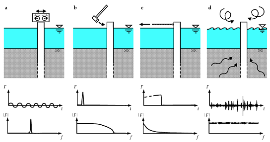
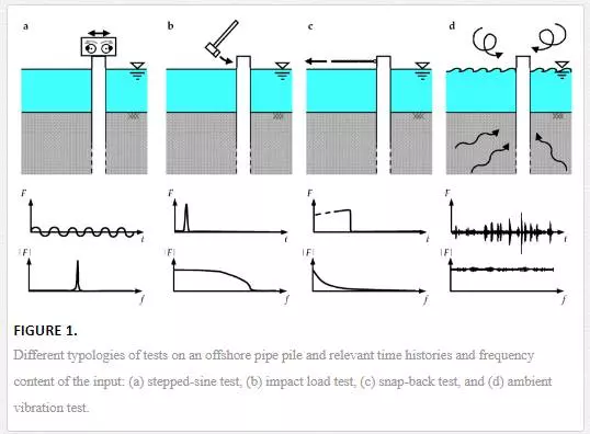
Several test typologies can be useful to identify the modal parameters of a soil-water-pile system; most of them come from the fields of aerospace and mechanical engineering and have been recently developed for applications in civil engineering fields. Those tests can be classified based on the input that can be artificially and expressly created for the test or can be naturally present in the ambient; in most cases, artificial input is applied at the pile head and can be measured, whereas ambient input is usually due to waves coming from soil, water, or air surrounding the pile and cannot be easily measured. In the sequel, the most useful and effective test typologies are described: stepped-sine and sweep-sine tests, impact load and snap-back tests among the typologies requiring an artificial input, and ambient vibration test as an example of tests based on natural input.The most popular typologies of testing are the stepped-sine and sweep-sine tests [9], also known as forced vibration tests, where the excitation force contains one single frequency at a time (harmonic signal) and either sweeps with a fixed frequency step or varies slowly but continuously within an established frequency range [10], allowing the structure to engage in one harmonic vibration at a time. The input is applied with mechanical or hydraulic shaker located at the pile head (Figure 1a), whereas the response can be recorded with strain gauges or accelerometers installed along the pile shaft. This testing is effective for studying the dynamic behavior of a soil-pile system under both low and high vibration levels characterizing even the nonlinearities of the system [9].
Another method, very popular because of its execution simplicity and low cost of the instrumentation required, is the impact load testing. In this case, the input is impulsive and is applied by means of a hammer (Figure 1b) instrumented with a load cell detecting the magnitude of the impact. The response can be recorded with accelerometers or strain gauges located along the pile length. The investigated frequency range depends on the stiffness of the hammer tip and of the pile surface; generally, a soft tip concentrates the impact energy at a low-frequency range, whereas a hard tip permits the investigation of a wider frequency range. The main limit of impact load testing is that only the linear elastic behavior of the soil-water-pile system can be investigated unless a heavy loading system is used as in the case of Statnamic test [11].The snap-back test (or free vibration test) can be viewed as a variant of the impact load test [10]. In this testing procedure, the load is gradually applied at the pile head by means of a steel cable pulled with a hydraulic jack (Figure 1c). Then, a quick release of the system can be obtained in two different ways: by cutting the cable with a blowtorch or by inducing the failure for traction of a steel pin placed along the cable between the jack and the pile; after the failure of the pin, which can be opportunely calibrated to obtain the desired load level, the pile undergoes a number of steadily decreasing oscillations around its equilibrium position. The load applied before the release is usually recorded with a load cell located in the loading apparatus, between the jack and the pile. The snap-back test may be performed at increasing levels of force allowing the investigation of the nonlinear behavior of the soil-water-pile system; on the other hand, a snap-back test can excite only a mode shape or a combination of mode shapes, which are generally relevant to the first natural frequencies of the system while the higher modes cannot be investigated.
In the ambient vibration testing, the system is excited only by natural vibrations (e.g. microtremors, wind, wave load, and anthropic activities) and artificial excitation is not needed (Figure 1d). This is the main advantage of this technique, which consequently requires small, light, and very portable instrumentation entailing a great reduction of costs and times for the test preparation. On the other hand, in order to record the very low amplitude vibrations induced by natural excitation, specific low noise accelerometers are required. Similar to the impact load test, the natural excitation is assumed to have a flat spectrum such as that of a white noise; therefore, the dynamic characteristics of the system can be investigated in a wide range of frequency even if, because of the very low level of vibrations, only the linear behavior of the system can be studied. In order to investigate the dynamic behavior of the system under a higher level of excitations coming from the ambient, particularly, propagating through the soil, two different strategies can be considered: large-scale blasting inducing artificial ground motion or natural soil motion induced by earthquakes. In the latter case, a permanent monitoring system must be installed on the system and should be equipped with a trigger system to start recording at the beginning of the seismic event.
Pile instrumentation
This chapter deals with some issues related to the instrumentation necessary for the dynamic characterization of open-ended pipe piles in marine environment. First, the quantities that can be measured and the instrumentation layout are discussed. Then, various typologies of transducers available in commerce and their characteristics are illustrated. Finally, some protection systems available to prevent malfunctioning caused by the marine environment are reported.
MEASURED QUANTITIES AND INSTRUMENTATION LAYOUT
Different measurement strategies can be adopted to characterize the dynamic behavior of open-ended pipe piles in marine environment: typology of sensors and instrumentation layout mainly depend on the objectives of the experimental campaign and also on the dynamic characteristics investigated, whereas the number of sensors depends essentially on the desired refinement of the expected results, e.g. the definition of the mode shape along the pile or the accuracy and reliability of the values of frequencies and damping ratios.
In order to identify the dynamic characteristics of a system, dynamic quantities such as accelerations and/or displacements should be measured; to do this, accelerometers and/or displacement transducers may be installed on the pile surface. In general, acceleration measurements are commonly preferred because acceleration is a absolute quantity and the accelerometer does not require a fixed external reference (necessary in the case of displacement transducer); furthermore, the numerical integration procedures required to obtain displacements from acceleration data are more stable and less sensitive to noise than the derivative procedures required in the opposite case. If possible, both accelerations and displacements should be measured; for example, in the case of snap-back tests, this permits to better catch both the quasi-static part of the test and the oscillation part of the signal. Instead of displacements or accelerations, even strains at the pile surface could be recorded by means of strain gauges; in this case, assuming the pile behavior to be linear, relative displacements can be derived according to the Euler-Bernoulli beam theory. Furthermore, it is often very important to record the pore pressure at the soil-pile interface during the pile installation and the dynamic test; this can be gained by inserting a pore pressure transducer in the pile shaft in such a way that the sensing element is in contact with marine soil.
The location where the sensors will be placed along the pile shaft plays a crucial role in the choice of the most adequate type of sensor. Generally, while sensors can be easily installed in the pile portion over the sea level (if any), greater difficulties must be overcome for the installation and protection of sensors along the submerged part of pile and, especially, along the part embedded in soil. In the latter case, it is not possible to directly measure the pile displacements by means of displacement transducers, whereas accelerometers and strain gauges should be used, paying particular care in their protection not only against aggressive environmental conditions but also against mechanical stresses, especially in the case of vibrodriving installation of the pile.The layout of sensors along the pile depends on many aspects that involve the distribution of sensors longitudinally along the pile shaft and along the perimeter of the transversal cross-section. In order to evaluate the pile motion, arrays of transducers can be located along the whole pile or just along the section of interest. For a better definition of the mode shapes, the measuring points should be located narrower in the proximity of discontinuities, such as at the water-soil interface, at the interface of soil layers having different stiffnesses, or in correspondence to changes in the pipe pile cross-section (Figure 2a). The length of the array depends on the input level as well as on the sensitivity of the sensor; in the case of input applied at the pile head, higher input energy levels and higher sensor sensitivity allow the monitoring of the pile to a greater depth.
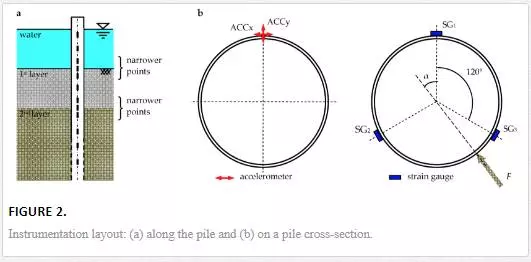
In order to capture the cross-section deformation of the pipe pile, several sensors should be installed around the circular perimeter; the number and layout of sensors depend on how many cross-sectional modes are of interest. However, excluding the sections close to the point where the input load is applied (stiffeners of the transversal cross-section may be added), the pile cross-section can be usually assumed to be rigid in its plane. In this case, to correctly evaluate the direction of the pile lateral motion and therefore of the applied horizontal input (e.g. the hammer impact direction), more than one sensor should be installed around a cross-section. In particular, neglecting the vertical component, if accelerometers are used, the input direction is known when two horizontal orthogonal acceleration components in one point are measured. On the other hand, if strain gauges are used, the pile motion direction can be calculated from the strain values measured by three sensors installed at the same cross-section and spaced 120° apart; assuming that the pile remains in the elastic range, the angle α between the direction of the load F (Figure 2b) and the line connecting SG1 to the center of the cross-section can be calculated according to the following formula:

Finally, it is worth noting that a good estimation of the applied loading (e.g. the load exerted by the jack in a snap-back test) can be calculated from the value of strains recorded by two strain gauges SGi and SGj installed along the same vertical in the portion of the pipe pile above the ground where the bending moment (and therefore the longitudinal strain) varies linearly with depth; the actual applied load is thus obtained from the following formula

where E is the elastic modulus, W is the section modulus, and Δh is the distance between the two strain gauges.
SENSOR TYPOLOGIES
STRAIN TRANSDUCERS
Strains can be measured with different transducer typologies; the most common are electrical strain gauges, vibrating wire strain gauges, and fiber optic strain gauges (Figure 3).
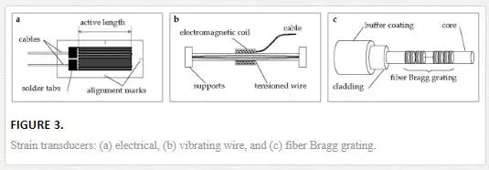
The electrical strain gauges, also known as foil strain gauges, are the most common sensors for strain measurements. A grid made of fine electric resistance wire printed on a polyamide foil constitutes the sensor element (Figure 3a). This sensor typology uses the relationship between the applied strain ε (ε = ∆L/L) and the relative change of strain gauge resistance ∆R [12], derived by the second Ohm’s law and described by the equation:

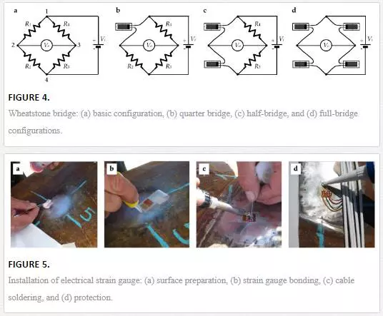
where R0 is the initial strain gauge resistance (usually 120 or 350 Ω) and k is the gauge factor checked experimentally (usually for metal strain gauge is about 2). To measure the resistance changes, a Wheatstone bridge circuit, whose basic configuration is reported in Figure 4a, is usually adopted. The four arms of the bridge are formed by the resistors R1 to R4 having the same nominal resistance value; the input voltage Vi is applied between point 1 and 4, whereas the output voltage Vo is measured between points 2 and 3. If all resistances are equal, then Vo is zero, whereas, if at least one resistance changes, then the bridge is unbalanced and the following value of output voltage can be measured:
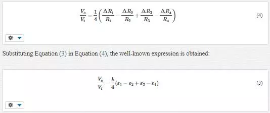
where εi is the strain measured by the strain gauge applied at the ith arm of the bridge. Three configurations are available for the measurements with strain gauges (Figure 4b–d) commonly called quarter bridge, half-bridge, and full bridge if one, two, or four resistances, respectively, are substituted with strain gauges. The latter two configurations permit the compensation of the temperature effects. In the case of large distances among measuring points and data acquisition system, the influence of lead resistances is not negligible and proper correction factor or shunt calibration [13] should be adopted. To obtain a reliable and correct measurement, a particular care is required in the installation of a strain gauge; the correct procedure is standardized and can be summarized in different stages involving the surface preparation, strain gauge bonding, soldering of the cables, and protection of the measuring point (Figure 5a–d, respectively).
In general, electrical strain gauges are considered the best cost-effective measurement solution and a well-supported technology for applications in typical short-range and controlled operational environments. However, for the monitoring of pipe piles in marine environment, the drawbacks are the not long life span and the increase of electromagnetic interference due to the voltage drop on long lead wires, which make this technology not optimal for long-term monitoring or for applications in which the measuring system cannot be installed close to the sensors.
The vibrating wire strain gauges permit the determination of strains by measuring the consequent change in the natural frequency of transverse vibration of a tensioned wire. The frequency is measured by plucking the wire with an electromagnetic coil connected through a cable to data acquisition system (Figure 3b). The installation on a pipe pile can be carried out welding the sensor ends at the pile shaft. The temperature effects can be compensated, thanks to a termistor (for reading temperature) located on the sensor case. The main advantages are the long-term stability and the high resistance to water intrusion and lighting damage, whereas the drawbacks are the sensor size and gauge active length, usually ranging 50–250 mm, which make the sensor not suitable when the strain at a precise point must be measured, and then, more importantly, the limitation to static measurements, which limits their use to the quasi-static part of tests, such as the pile lateral pulling phase before the release in a snap-back test.The strain gauges based on the optical fiber technology are the most innovative strain sensors and may be the most powerful ones. The optical fiber is usually composed of three layers: fiber core (constituting the sensing element), cladding and jacket. The perturbation in strain causes corresponding changes in terms of amplitude, phase, frequency, wavelength, and polarization in the optical properties of the transmitted light [14]. Among different technologies, the sensors most used in civil engineering are the Fabry-Perot strain gauge sensor, based on white-light cross-correlation principle, which allows the local measurement of the strain between two fixed points along the fiber with high resolution, and the fiber Bragg grating (FBG) sensor (Figure 3c) in which a series of localized changes in the refractive index of the glass core of the fiber constitute the sensing part. FBG sensors are especially fit for strain measurements of pipe piles in marine environment due to high resolution, quasi-distributed sensing, temperature compensation, good anti-corrosion ability, and long-term stability; these last two characteristics permit to extend their use even to long-term monitoring [15]. The main drawbacks are the costs related to the optical fiber and especially to the demodulation system, which, however, are expected to decrease in the near future.
ACCELERATION TRANSDUCERS
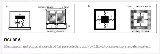
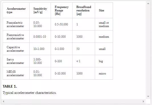
An accelerometer is a device that converts a mechanical acceleration into a proportional electrical signal, usually voltage output. Commonly, an accelerometer is composed of a case and a seismic mass connected with it by means of an elastic sensing element (Figure 6a). Several accelerometer typologies are available in commerce: piezoelectric, piezoresistive, or capacitive accelerometers depending on the physical phenomenon characterizing the sensing element. Recently, the so-called MEMS (micro electro-mechanical systems) accelerometers have been developed; these sensors are based on the same physical phenomena of the above-mentioned sensors but are realized exploiting microfabrication techniques (Figure 6b). Finally, the servo (force balance) accelerometers are available; these sensors are composed of a case with seismically suspended mass balanced by a magnetic coil, which generates a restoring force to maintain it in the null position; when the null detector (e.g. a capacitance-type transducer) reveals a displacement of the mass, a servo amplifier increases the coil current proportionally to the external applied acceleration [16].To suitably select an accelerometer, many parameters have to be considered: the sensitivity, i.e. the relationship between sensor voltage output and acceleration; the frequency range, i.e. the range over which the sensitivity is nearly constant; the maximum value of acceleration measurable by the sensor; and the broadband resolution, i.e. the smallest acceleration that the sensor can detect. The maximum value of measurable acceleration and the broadband resolution may often depend even on the signal conditioners and data acquisition systems utilized.
The required characteristics should be determined according to expected frequency values obtained by means of preliminary simulations with analytical or finite-element models and checked, if possible, with preliminary tests. Furthermore, environmental conditions (such as temperature) and sensor size have to be taken into account to choose the better sensor type, especially in the case of sensors that will be located in the submerged or embedded part of the pile.
In Table 1, the typical characteristics regarding the different technologies of sensors available in commerce are listed [17]. When accelerations are characterized by low-frequency content, piezoresistive, capacitive, or servo accelerometer is the better solution. In the case of tests with low-intensity input, piezoelectric or servo accelerometers have to be preferred, thanks to their high sensitivity and good broadband resolution. Finally, when sensor costs must be minimized and/or the smaller size is required, the MEMS technology furnishes the best solution.
Finally, it is worth remembering that, even if the mounting method affects the useful frequency range of an accelerometer [17] reducing the upper limit (kHz as magnitude order), all common available methods (cyanoacrylate, dental or epoxy cement, stud mounting, wax, permanent magnet, and adhesive) are suitable for investigating low-frequency range such as that typical for first natural frequencies of an open-ended pipe pile in marine soil under lateral loads. Generally, the cement mountings are used for accelerometers applied permanently in the submerged and embedded part of the pile, whereas permanent magnets or wax are preferred for accelerometers located over the sea level due to easy application or removal of the sensor.
DISPLACEMENT TRANSDUCERS
The measurement of displacements at the pile head can be essential, especially during the quasi-static part of a snap-back test. Among a great number of different displacement transducers available in commerce, those most common and able to capture both dynamic and static values are potentiometers, inductive transducers, and linear variable differential transformers (LVDTs). The latter, one of the most known and utilized sensor, is characterized by a very fine resolution (in good environmental conditions), has a frequency range up to some kilohertz, and guarantees high robustness. An LVDT consists of a primary solenoidal coil and two secondary coils; a movable ferromagnetic core is placed parallel to the axis of the cylindrical case and it is attached to the object to be measured, whereas the case is fixed externally to the vibrating system. The primary coil is excited by an alternating current inducing a voltage in secondary coils, which is proportional to the displacement of core.
PORE PRESSURE TRANSDUCERS
When the value of the pore water pressures acting at the soil-pile interface has to be investigated, two different sensor typologies could be used: standard size pressure transducers or miniature pressure transducers. The latter is usually preferred because the small size facilitates the mounting of the transducer in the pile thickness reducing compliance errors and the chance of damage and increasing the frequency response of the measuring system [18]. A pore pressure transducer consists of a thick diaphragm mounted in a case and externally protected by a porous disk. The diaphragm can be equipped with sensing elements or it can be itself the sensing element. In the case of piezoresistive pore pressure transducer, widely used in the geotechnical field, strain gauges are built-in or applied on the diaphragm and connected to a Wheatstone bridge to obtain an amplification of the signal and the temperature compensation.
PROTECTION OF SENSOR AND CABLING
The correct selection of the more appropriate systems and products to protect instrumentation and connecting cables is a key point in every experimental campaign, especially when such operation is performed in situ and, particularly, in marine environment. In order to make the correct choice among several products and covering agents available in commerce, various considerations should be done regarding the ambient conditions, the duration of the measurement, and the possible interference of the protection with the specimen [19]. The ambient conditions of both sites where the pile is instrumented and the site where it will be installed should be carefully taken into account. Sensors applied on pile embedded in marine environment are subjected to several types of aggressive agents [20]: mechanical stresses and erosion due to the effects of waves and tides, climatic agents due to variations of temperature, and chemical attacks carried out by sulfate and chloride attacks. Furthermore, the handling and installation phases of the pile could cause important stresses on the pile shaft due to impacts, loads, and frictions. The required lifetime of the instrumentation must be determined based on the duration of measurements. Tests performed to characterize the soil-water-pile system can be made only on time; they can be periodically repeated or a continuous monitoring may be carried out to investigate variations in time of the dynamic parameters. Especially, in this last case, the protection must be designed considering a proper lifetime of the system. Finally, an accurate isolation from electromagnetic fields allows the reduction of noise, whereas a protection by the moisture avoids signal drifts permitting a greater accuracy and precision of the measurements.
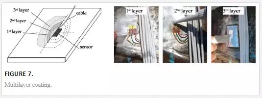
Several precautions should be taken in the application of protective coatings. The installed transducer must be in a perfect condition before being covered. Trapped humidity, perspiration, and flux residue from soldering can lead, sooner or later, to inaccurate measurements or, in some cases, even to complete failure. Efficient protective covers are not only a seal against outside humidity, but they also seal in trapped humidity. For that reason, laboratories or protected ambient should be preferred during sensor installation; furthermore, the first coating layer should be applied as soon as possible after sensor bonding to reduce the contamination of the measuring point with impurities and humidity. When the application of the transducer has to be carried out in humid ambient condition due to bad weather (especially when the pile instrumentation is carried out in situ), the measuring point should be dried with hot air gun, taking care not to exceed the safe operating temperature of the transducer. The area surrounding the installed transducer should maintain the same quality over the whole useful lifetime of the instrumentation. Scratches and impurities allow the penetration of aggressive agents that could damage the sensor; this area should be carefully cleaned and the covering agent should adhere perfectly the surface and cover an area some centimeters larger than the transducer to protect it adequately. In particular, this area should include the cable ends (even underneath) and the cable connections (intrabridge wiring and jumper leads), which, in some cases, can constitute preferential pathways for moisture. Sometimes, one type of covering agent is not sufficient, and multiple coating layers can be combined by applying the first coating directly on the surface of the transducer and then applying the other layers, taking care that each coating covers a portion larger than the previous one (Figure 7).
Transducers applied on a pile embedded in marine environment are exposed to different conditions depending on their location along the pile shaft: over the sea level, submerged in the sea, and embedded in the soil. Different protections are needed in each case. For the transducers installed over the sea level, a protection from humidity and rain is necessary and it can be obtained with a sealed box, for normal size accelerometers, or with protective coating for MEMS accelerometers and strain gauges. In order to seal a measuring point, several products can be used: polyurethane varnish provides a protection against dust, ambient humidity, and oil (usually, it is used as the first insulating layer under the other covers); nitrile rubber varnish is useful in the substitution of polyurethane varnish as a protection in ambient with oil, petrol, and liquefied gases, excluding oxygen; the silicone rubber increases the mechanical protection but is not resistant to oil.For the strain gauges or MEMS accelerometers installed along the submerged pile section, the protection against marine environment can be obtained with one of the products listed above coupled with butyl rubber (or plastic putty) to guarantee a better waterproofing; an aluminum layer is placed above all as a diffusion additional barrier enhancing the long-term protection.
Finally, sensors installed in the embedded part of pile can be protected with the same covering agents used in the submerged part. When pile handling or installation phases represent the potential causes of stresses on the pile shaft, the measuring points and cables can be protected with additional mechanical protections, e.g. metallic profiles or foam materials.
In the case of optical fibers and Bragg grating sensors, they could be located along ridges or grooves already present or realized on purpose along the pile to provide a good mechanical protection. Furthermore, in order to ensure a higher chemical and mechanical protection, the optical fibers could be inserted into a tubing covered with a thick layer of resin; some special precautions can be taken for the measuring point over the Bragg grating sensors by means of different coating protective layers.
Signal processing techniques
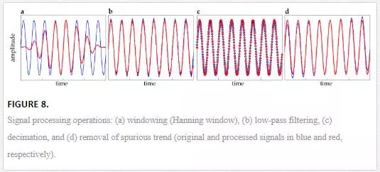
Before performing the modal analysis, all the recorded data must be suitably processed by means of signal processing techniques. Several operations can be carried out on the raw signals to reduce noise, to limit bothering due to leakage and aliasing, and to eliminate spurious frequency contents. In this part, the operation useful for test typologies discussed above will be summarized.The windowing consists of the application of weighting function to the time histories in order to reduce the amplitude of initial part, final part, or both (Figure 8a). The use of windowing is a practical solution to the leakage problem associated with the use of discrete Fourier transform of data. Regarding sinusoidal signals or random signals, such as those derived by stepped- or sweep-sine testing and ambient vibration test, the use of Hanning, Hamming, or Kaiser-Bessel window forces the signal to zero at the ends allowing to overcome leakage problem in the computation of the Fourier response function. For transient signals, obtained by impact load or snap-back tests, the exponential window can be used to attenuate the signal in the final part, especially for low damped systems. A boxcar limited and centered on the impact can be applied in order to eliminate the noise from the initial and final parts of the signal. The window functions must be applied with care, as they produce signal modifications that sometimes lead to erroneous results (i.e. the exponential window adds a damping contribution to the signal decay).
Filtering operation can be seen as a windowing carried out in the frequency domain rather than in time domain [10]. Filters are applied when some frequency contribution of the signal must be attenuated (Figure 8b). The main characteristics of a filter are the cutoff frequencies, that define what frequencies are attenuated and what frequencies can pass through the filter, and the order of the filter that controls the roll-off features near these critical frequency regions. Different filters are available: low-pass filters, high-pass filters, band-pass filters, and band-stop filters are the most suitable for our purposes. Low-pass filter is applied during the decimation of the signal in order to eliminate the frequency content over the cutoff frequency and thus avoid aliasing phenomena (so it can be considered an anti-aliasing filter). Furthermore, the low-pass filter is used to cutoff the high frequencies due to the cross-sectional deformation of the pipe pile. Band-pass filter is useful when only a contribution in a finite frequency range have to be analyzed. Finally, band-stop filter can be used to eliminate spurious frequencies. As the windowing, filtering operations cause signal modifications that have to be carefully evaluated.The decimation is used to reduce the sampling frequency of an acquisition (Figure 8c). When the original data are sampled with a too high rate, decimation can be performed in order to decrease the number of data and to consequently speed up the successive analyses. The decimation is a two-step procedure requiring previously a low-pass filtering with a cutoff frequency below the Nyquist frequency (half the final sampling frequency) and then a downsampling of the data at the final sampling frequency. The decimation factor is the ratio between initial and final sampling frequencies.Offsets or spurious trends can affect the signals due to many reasons, first of all, the temperature (Figure 8d). The offset can be removed simply by subtracting the mean value of time series, whereas spurious trends need of a more complex procedure such as the fitting of the data with a low-order polynomial using a least-squares procedure and then subtracting the obtained values to the original time history.
The averaging is mainly used when the input applied is characterized by low intensity (i.e. for impact load test and ambient vibration test) and the signals are characterized by a low signal-to-noise ratio. By averaging different time series, it is possible to remove the spurious random noise from the signals [10].
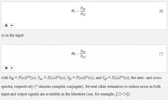
The discrete Fourier transform (DFT) is may be the most powerful tools in signal processing, allowing an early raw evaluation of the signal properties and even the modal parameters of a pile or other structures (i.e. with peak picking method). The DFT permits to convert a time series into the frequency domain obtaining the frequency spectrum of the signal. The frequency resolution ∆f of the computed spectrum depends on the time length T of the original signal from the well-known relationship ∆f = 1/T. The inverse discrete Fourier transform IDFT performs the inverse operation furnishing the time history relevant to a frequency spectrum. In the signal processing software, the DFT and IDFT are efficiently calculated, thanks to the fast Fourier transform (FFT) algorithm based on the Cooley and Tukey’s study [21]. Finally, the frequency response function (FRF) represents the dynamic behavior of the system and can be defined simply as the ratio between the Fourier transform of the system response X(ω) and of the applied input F(ω). Different FRF estimators, available in the literature [9], are very useful when highly noisy data have to be processed. These estimators provide the reduction of the noise in the output
Experimental modal analysis
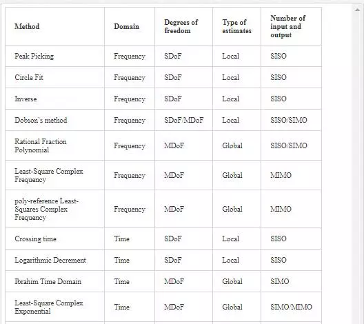
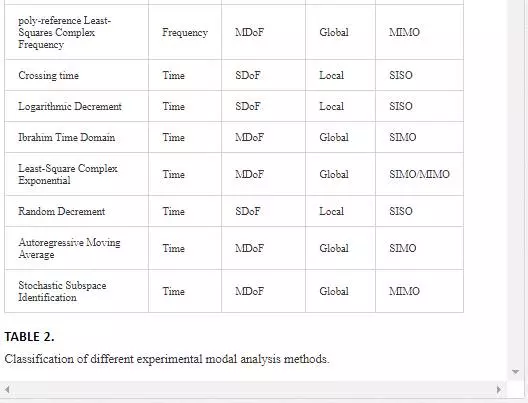
Experimental modal analysis provides the extraction of the modal parameters (natural frequencies, damping ratios, and mode shapes) of a linear time-invariant dynamic system starting from measured vibration data [9]. The theoretical basis of the technique is based on the recognition of the relationship between the vibration response at one location and excitation at the same or another location as a function of excitation frequency. This relationship can be represented, in the frequency domain, by the FRF or, in the time domain, by the impulse response function (IRF). The FRF is the Fourier transform of a response measurement normalized by the Fourier transform of the input and the IRF is the free vibration response of the structure. The passage from FRF to IRF can be performed by means of the IDFT.In the last decades, several methods have been developed in the field of the experimental modal analysis. The classification of these methods can be based on the working domain, time or frequency, on the number of the degrees of freedom used by the model, single degree of freedom (SDoF) or multidegree of freedom (MDoF), and on the number of inputs and outputs, single input and single output (SISO), single input and multiple output (SIMO), and multiple input and multiple output (MIMO).
Many of the basic methods working in the frequency domain use different plots of FRFs in order to identify the modal parameters in a simple way. Peak-picking method, the simplest SDoF method working in the frequency domain, estimates the natural frequency from the peak amplitude of FRF. The half-power bandwidth permits the damping ratio estimation from the width of the peak in the graph of FRF amplitude. Furthermore, circle fit method, [25, 26], estimates the modal parameters working in the Nyquist plot (Re-Im). Finally, the most advanced methods working in the frequency domain are the rational fraction polynomial (RFP) method [27], Dobson’s method [28], inverse method [29], least-squares complex frequency (LSCF) [30], and poly-reference least-squares complex frequency (pLSCF) [31] methods. These methods are based on a curve fitting of the measured FRF (or FRFs for MDoF systems) using an analytical model of the measured structure. A possible analytical expression of the FRF for a MDoF with input applied in j and response measured in i is

where rAij is the residue, ωr is the natural angular frequency, and ξr is the damping ratio (viscous) of the rth mode, respectively, and Rij is the residual term to take into account the other modes. The time domain methods use time response data that can be represented by the IRF for impact load or snap-back tests or by the recorded data during the operational condition for ambient vibration tests. Crossing time and logarithmic decrement are the simplest methods for the estimation of natural frequencies and damping ratios, respectively. These two methods can be performed by consulting the IRF graphs after having isolated each single frequency contribution by means of band-pass filters. The crossing time method uses the zero passing of the signal in order to evaluate the period (the time interval between two crossing is equal to half of the period), whereas the logarithmic decrement estimates the damping using the free decay of the signal (the damping is equal to the natural logarithm of the ratio between the ith and i+nth maximum of the signal divided by 2πn). The most powerful time domain methods are based on the recent developments in the control theory. Many of these are implemented in commercial software products for experimental modal analysis: Ibrahim time domain (ITD) method [32–34]; least-squares complex exponential (LSCE) method [35], working with IRF; and random decrement (RD) method [36–38], autoregressive moving average (ARMA) method [39, 40], and stochastic subspace identification (SSI) method [41], working with measured random response. In Table 2, the most useful methods are listed with their main characteristics.
Case study: Lateral loading tests on near-shore pipe piles in marine environment
This section is devoted to a concrete case study: an experimental campaign carried out on near-shore open-ended pipe piles at the ‘‘Mirabello’’ harbor in La Spezia, Italy. The general aim of this campaign was to detect the complex dynamic soil-pile interaction, taking into account the influence of the specific construction technique that can affect significantly soil properties close to the piles. In particular, the experimentation was performed in order to (i) develop new field test procedures to gain information on the soil dynamic properties and on pile-soil-pile dynamic response that can be used directly in seismic design of pile foundations and (ii) calibrate and validate analytical and numerical procedures and develop new empirical methods for soil-pile interaction analysis. Some details about the site together with the pile instrumentation system and the relevant chemical and mechanical protections are here reported. More details can be found in the work of Dezi et al. [42, 43].
SITE, TEST FIELD, INSTRUMENTATION, AND TEST SET-UP
Site: The site selected for the tests was next to “Porto Lotti” at the tourist port “Mirabello” in La Spezia, Italy. This area comprises several piers and about 1000 new berths for boats and ships from 14 to 60 m long. The superstructure consists of a grid of precast prestressed beams, which supports a cast in situ concrete slab. The foundation is composed of about 500 vibrodriven steel pipe piles ranging from 609 to 711 mm in diameter, from 11 to 13 mm in thickness, and from 20 to 45 m in embedded length. Several site explorations (1973, 1981, 1991, 1992, and 2008) were carried out before the construction of the tourist port. A large volume of soil was investigated by means of laboratory tests such as the odometer test, in situ tests conducted up to a maximum depth of about 50 m, including the dilatometer Marchetti test (DMT), cone penetrometer test (CPT), piezocone test (CPTU), standard penetration test (SPT), vane tests (FV), and multichannel analysis of surface waves (MASW).
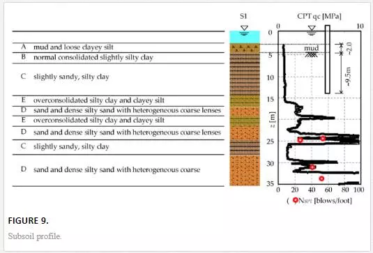
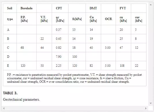
The soil stratigraphy can be subdivided into six main layers. The upper layer, Layer A, consists of mud and loose clayey silt, with water content greater than the liquid limit. Normal consolidated slightly silty clay was found in the second main layer, Layer B, whereas the succeeding layer, Layer C, is composed of slightly sandy silty clay. Layer D consists of sand and dense silty sand, including scattered shell fragments and heterogeneous coarse lenses. Layer E includes overconsolidated silty clay and clayey silt. Under level D to the end of the borehole (about a depth of 50 m), there is a compact layer of clayey sandy gravel. The results of these investigations are summarized in Figure 9, where the soil stratigraphy and the CPT performed
nearby the test site are reported, and in Table 3, where the main soil properties of each soil layer are presented.
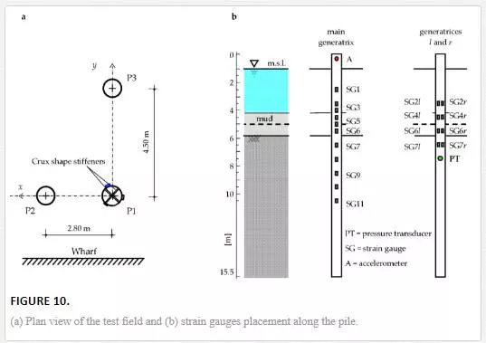
Test field: As shown in Figure 10a, the test field consisted of three steel pipe piles vibrodriven for a depth of 9.5 m into soft marine clay. Piles were 15.5 m long and the pile head elevation was 1.0 m above mean sea level (m.s.l.). Pile P1 was characterized by a diameter of 711 mm and thickness of 11 mm, whereas piles P2 and P3 were characterized by a diameter of 609 mm and thickness of 10 mm; the head of the piles was kept free and the head of pile P1 was stiffened with two steel profiles, welded in a crux shape. The piles were arranged in an “L”-shaped horizontal layout characterized by different distances between pile P1, located at the “L” corner, and piles P2 and P3. It is important to point out that characteristics and location of piles P2 and P3 were practically irrelevant to comprehend the single pile behavior, although it was useful to investigate the pile-soil-pile dynamic interaction. It is worth noting that, based on the results of the geotechnical investigations, the soil strength profile can be reasonably considered as uniform over the pile embedment length.Pile instrumentation: As regards the sensors, their characteristics were chosen on the basis of preliminarily finite-element analyses performed to define the amplitude-frequency response of the soil-water-pile system. The sensors used to instrument the piles were electrical strain gauges, installed along the pile P1 to measure the longitudinal strains, accelerometers located close to the top of the piles to measure the vibrations of the pile head, and a pore pressure transducer on the pile shaft. In detail, as shown in Figure 10b, a total of 19 strain gauges were placed along three generatrices of the pile P1, spaced 120° apart to capture the cross-section average strains (elongation and curvature of the pipe); 11 strain gauges were located along the main generatrix and 4 along each of the two secondary generatrices. Narrower measure points were considered for the pile section where maximum curvatures were expected. A uniaxial accelerometer was located at 0.3 m from the top of the pile in such a way that the measured acceleration is in the same direction of the lateral input. The measurement chain was also composed of amplifiers, signal conditioners, one spectrum analyzer, two data acquisition systems, and a computer with dedicated software.
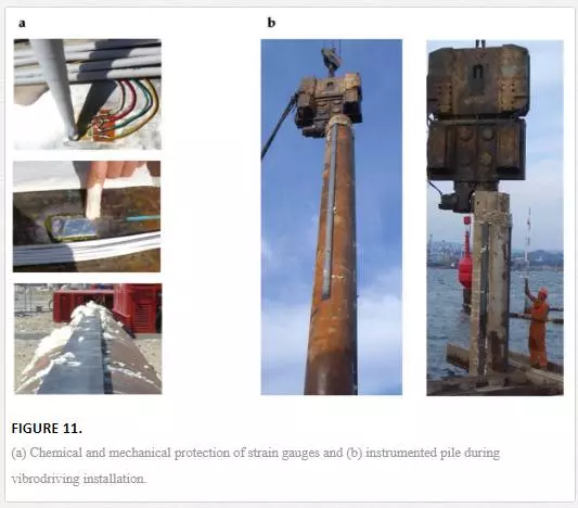
During installation, the measuring instruments were carefully protected both chemically and mechanically from the marine environment and pile vibrodriving. Cables and strain gauges were first waterproofed and protected with three products, a polyurethane paint and silicone rubber covered by aluminum foil coupled with kneading compound (Figure 11a), and then protected by means of UPN steel profiles welded along the three generatrices, sealing the space between pile and UPN with polyurethane foam (Figures 11a and 11b).
Several hours after pile vibrodriving and during the first test series, all the strain gauges, except one, were working properly. The pressure transducer worked only for several hours due to waterproofing malfunction. In the second series (after 10 weeks from pile installation), another strain gauge appeared not be working correctly. Despite this, the procedure adopted in this experimental campaign for the strain gauge installation was observed to be very effective to protect the gauges in the aggressive marine environment over the whole period of the tests (about 3 months).
TEST TYPOLOGIES
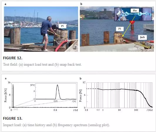
Two test series were conducted at two different time instants: the first 1 week after the pile installation and the second after 10 weeks. The tests were repeated to evaluate differences with time in the dynamic behavior of the soil-water-pile system.Two different typologies of test were performed: impact load and free vibration tests (Figures 12a and 12b). Impact load tests were conducted at two different time instants: the first series 1 week after the pile installation and the second series after 10 weeks. The snap-back tests were performed after the second series considering different force levels.Finite-element simulations and several preliminary in situ tests demonstrated that the impact of the hammer with medium-low hard tip induced values of accelerations at the pile heads and longitudinal strains along the pile, measured by the transducers, greater than the ambient-noise. With this hammer, a maximum impact force of about 50 kN was reached. A typical time history of a medium-intensity impact measured by the load cell of the hammer is shown in Figure 13a in which a zoom of the peak is also reported. The corresponding frequency spectrum, shown in Figure 13b, is characterized by a constant force level up to about 100 Hz. Therefore, this hammer permitted to investigate the soil-water-pile behavior in a wide range of frequencies, ranging between approximately 0.5 and 100 Hz. A sampling rate of 10 kHz was chosen to achieve high resolution in time domain, and an acquisition time duration of 2 s was considered to catch the entire duration of the pile oscillation.
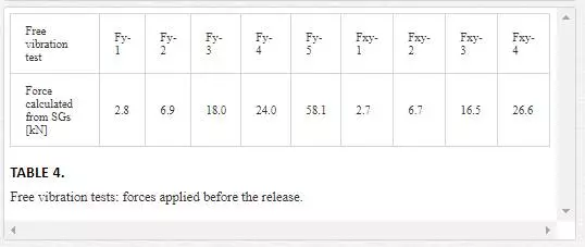
The free vibration tests were performed to investigate the dynamic behavior of the system at different strain levels by varying the level of force that is usually imposed with a standard hydraulic actuator. In this experimental study, the load was applied using a double-acting jack with a capacity of about 400 kN, placed on the wharf and connected to the pile P1 by means of steel cables. The wharf provided the reaction for the device. The quick release was achieved, thanks to the failure for traction of a steel pin placed along the steel cable between the jack and the pile P1. The cross-section of the pin was opportunely calibrated to obtain the desired load level. After the pin failure, the pile underwent a number of steadily decreasing oscillations around its equilibrium position.An analogical pressure transducer was used to sense the hydraulic oil pressure in the pump actuating the jack. Unfortunately, due to its low sensitivity and to the friction between the ram and cylinder wall (amplified by environmental conditions), the adopted measuring system was affected by raw approximation. A more precise estimation of the actual loading exerted by the jack was obtained from the values recorded by two strain gauges located in the portion of the pile above the ground where the bending moment (therefore the longitudinal strain) varies linearly with depth. The actual applied load was thus obtained from the analytical procedure presented above. In Table 4, the value of the force producing the traction failure of the pin (maximum quasi-static force) and the quick release of the pile obtained for each test is reported.
Before the tests, the sea water and soil levels inside and outside the pipe were measured, the ambient noise mainly due to marine waves was registered, and preliminary tests were conducted to set up the data acquisition system, entity of the impact, and proper gains for the accelerometer signals.
TEST CONFIGURATIONS
The impact load tests of both series were carried out considering three different test configurations, varying the direction (x, y, or diagonal, identified with xy index) of the horizontal impact at the head of pile P1 and the measuring direction of the accelerometer at the pile head. In particular, Hi denotes a test in which the hammer impacts the pile along the ith direction, while the acceleration is measured in the same direction. In Hx, Hy, and Hxy tests, the hammer impacted the pile along the x-, y-, and xy-directions, respectively, and the accelerometers were positioned in several configurations. For each test configuration, sets of 10 horizontal hammer impacts were applied and the time histories of the impact load, acceleration at the pile head, strains, and pore pressure along the pile were recorded.The free vibration tests were carried out with two different configurations, the pile P1 released (i) along the y-direction, aligned with the line connecting piles P1 and P3, and (ii) along the xy-direction, angled at 45° with respect to the y-direction, namely, Fy and Fxy tests, respectively. Tests along the x-direction were not performed because of difficulties in adequately arranging the traction system. A time acquisition of 4 s, including a pretrigger of 2 s, and a sampling rate of 5 kHz were used. Tests were repeated for different load amplitudes: 5 tests in the y-direction and 4 tests in the xy-direction for which different calibrated pins were used. Tests were conducted over 1 day (after the impact load test), firstly Fy tests and then the Fxy ones.
EXPERIMENTAL RESULTS AT VERY SMALL-SMALL STRAIN
Results of impact load tests and free vibration tests at low force level are here reported in terms of strain gauge measurements with the aim to discuss the dynamic behavior of the soil-water-pile system both at very small and small strains, respectively. First, the qualitative features of all the signals and the differences among signals recorded at various measuring points along the pile are discussed and then the modal properties of the soil-pile system in terms of frequencies and damping ratios will be reported and commented.
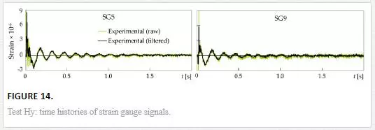
The time histories of the longitudinal strains recorded on pile P1 with SG5 and SG9 for an impact load of the test Hy during the first series are shown in Figure 14 with a green line and with a black line after signal filtering. The initial part of the signals, especially for strain gauges nearer the pile top, is characterized by high-frequency content due to cross-sectional deformation of the pipe. Therefore, the experimental signals were filtered by a Butterworth low-pass filter with a cutoff frequency of 100 Hz to nearly eliminate the effects due to cross-sectional deformation and noise, which are mainly characterized by high-frequency content
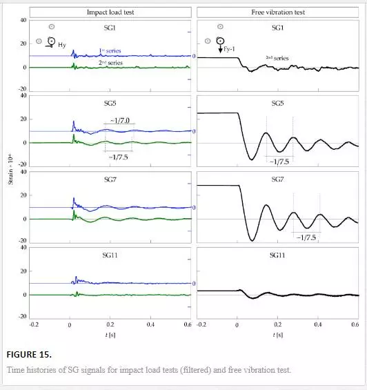
The measurements recorded by some strain gauges along the main generatrix for one of the 10 impacts of the test Hy during the first and second test series are reported in the left column of Figure 15 in blue and green, respectively. Each strain gauge signal exhibits a first peak with high amplitude due to the impact. The peak is characterized by a time delay due to the traveling time of the impulse, which increases with the distance of the measuring point from the hammer impact point. After the peak, the measurements show a damped harmonic oscillation at the frequency of the first bending mode of the system. With reference to the harmonic oscillation, the strains, which are proportional to the longitudinal bending moment, reach the maximum values for sensors located just below the soil surface (SG7) while decreasing in depth and near the pile head, where the bending moments are smaller; oscillations are practically null at SG1 and SG11, where strains are too small to be captured by sensors, considering their sensitivity and noise. The trends of the strain signals at the pile head are less smooth than those recorded at other locations due to residual ambient noise and radial-circumferential modes. Lower values of strains are registered in the second test series probably due to a lower energy content of the impacts. Disregarding the negligible differences just after the first peak, the response obtained from the two different series is qualitatively very similar. However, it can be observed that the period of the damped harmonic oscillation is shorter for the test of the second series.
The time histories of the first snap-back test (right column of Figure 15) show nearly constant values before the release due to the fact that the load is imposed in a quasi-static manner. After the quick release, free damped oscillations of the pile are manifested at nearly the first natural frequency of the soil-water-pile system (obviously, this result is also evident when plotted in the frequency domain). It worth noting that the values of strains obtained from the two test typologies differ of about one order of magnitude. However, the results are comparable and very similar from a qualitative point of view. The damped harmonic oscillations are practically proportional, and maximum values of strains, proportional to pile bending moment, are attained in the pile section located just below the soil surface (SG7) for both tests.
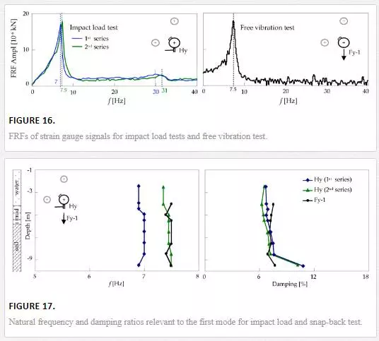
The modal properties of the soil-water-pile system, such as natural frequencies and damping ratios, were obtained by means of experimental modal analyses using the measured excitation applied to the pile head and the system response measured by strain gauges at various locations. Both the excitation and response time histories were transformed into the frequency domain to define FRFs. Natural frequencies were obtained by means of the peak picking method, selecting the frequencies corresponding to the peak values of the FRF amplitude. As an example, the FRFs relevant to SG5 obtained for the two tests are reported in Figure 16. The left graph shows the averaged FRF relevant to the 10 signals recorded by SG5 during Hy tests; the two clear peaks identify the first two natural frequencies of the soil-water-pile system. It is worth noting that the second series are characterized by higher values of the first and second natural frequencies. Analogously, the right graph reports the FRF of the signal recorded by SG5 for the snap-back test Fy-1; the FRF is not smooth because it was obtained from one signal and not averaged. In this case, the peak defining the first natural frequency is clearly identified, whereas the peak relevant to the second natural frequency is not evident due to the fact that the pile was released from a deformed shape similar to the first mode shape and, consequently, superior modes were only slightly excited. It is also worth noting that the first natural frequency obtained from test Fy-1 is coincident with that obtained from the second series of Hy test. As regards damping ratios of the soil-water-pile system at small strain, they were estimated from the strain gauge signals by means of the logarithmic decrement, working in time domain. The procedure was applied considering the first eight peaks to obtain a mean value representing the damping of the system during almost the entire oscillation of the pile. Figure 17 shows the natural frequencies and the damping ratios relevant to the first mode. It is important to observe that the second campaign is characterized by higher values of the first natural frequency and by slightly lower values of the damping ratio relevant to the first mode. The increase of the natural frequency values and the decrease of damping ratio values, obtained 9 weeks after the first test series (10 weeks after the vibrodriving), demonstrate an increase of the system stiffness (therefore, minor strains and, then, minor damping), which may be attributed to the soil reconsolidation subsequent to the pile vibrodriving installation. In fact, the vibrodriving technique induces excess pore pressure during installation and subsequent consolidation in the soil surrounding the pile.
In the second test series, very close values of frequency along the pile were obtained for both tests along the y-direction; this confirmed that the system behaves in elastic manner in both cases even if the strain level induced by snap-back tests is about one order greater than that of impact load tests. With reference to mean damping ratios, the average value among all the SGs obtained from the free vibration test is very close to the one obtained from impact load test, 7.2% for both Fy-1 and Hy. It can be noted that the values of damping ratio relevant to each SG signal tend to increase with depth.This study suggests that both test typologies, impact load and free vibration tests, are effective to evaluate the linear behavior, identifying the dynamic properties, of a near-shore pile driven in soft clay. Other test typologies could have been functional for the same purpose, such as the ambient vibration and/or forced vibration test. The first typology permits to evaluate natural frequencies and relevant damping ratios at very small strain, whereas the second one furnishes a higher excitation level that guarantees a more accurate measurement of the dynamic characteristics at low strain level. Furthermore, forced vibration test allows the excitation of higher-order modes that cannot be identified with other test methods.
RESULTS AT HIGHER STRAIN LEVEL: FREE VIBRATION TEST AT INCREASING LOAD LEVEL
To study the dynamic behavior of the soil-water-pile system at higher strain and to investigate the effects of soil nonlinearities, free vibration tests at four higher load levels were performed; the maximum force (58.1 kN) is about 20 times the minimum one (2.8 kN) as reported in Table 5. In this section, some results in terms of strains (measured values and FRFs) and dynamic properties of the system (frequencies and damping ratios) are reported.
Figure 18 shows the strains (and bending moments that are proportional to strains) measured along the pile by SGs for different loads just before the quick release. The continuous line is obtained, for each level of force, by interpolating the experimental data and allows obtaining an estimation of the maximum value of strain attained along the pile and its location (Table 5). As the load level increases, a progressively moving down of the location of the maximum strains is observed. This may be due to the formation of gap at the soil-pile interface. With regards to the instrumentation used in this study, the findings obtained in the linear and nonlinear fields showed that, thanks to a meticulous and accurate protection, the electrical strain gauges can provide reliable measurements even if the experimental campaign is quite extensive (few months) and in marine environment, permitting to obtain interesting results both in time and frequency domain.
Furthermore, during this experimental campaign, an abundant number of sensors were used and preliminary FEM simulations were conducted to define the correct location of sensors. For this reason, the definition of the dynamic properties of the system in the linear and nonlinear fields was successful. Thus, it is very important to define correctly the number and the location of sensors because, some time, limited discrete measuring points can be insufficient to capture completely the nature of the strain variation. To overcome this problem, optical fiber cables can be used instead of traditional strain gauges, providing practically continuous strain information along the pipe [44].
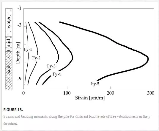
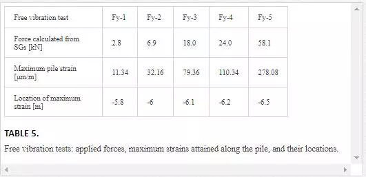
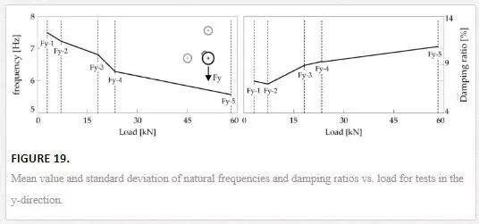
Figure 19 shows the mean values of the first natural frequencies and damping ratios obtained from free vibration tests at different load levels considering all the SGs of the main generatrix. The decrement of the natural frequency and the increment of the damping ratios with the load level are clearly evident in all the cases. The results could have been obtained even with forced vibration tests that permit the evaluation of the dynamic behavior at different strain levels depending on the characteristics of loading system. In particular, forced vibration test, even if more expensive and time-consuming, generally allows a more accurate evaluation of the dynamic parameters.
IMPEDANCE FUNCTION OF THE SOIL-WATER-PILE SYSTEM
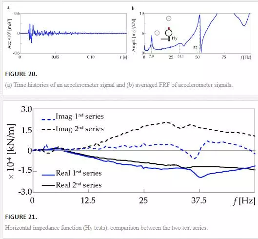
Impedance function represents the complex stiffness of the soil-water-foundation system under dynamic loads. In this research, the horizontal impedance of the soil-water-pile system was identified as the ratio, in the frequency domain, between the impact load applied at the pile head along a direction orthogonal to the pile axis and the resulting displacement at the pile head along the same direction. Displacements were derived from the recorded accelerometer signals by means of a double discrete integration in the time domain. Thanks mostly to the used high-fidelity modern sensors and data acquisition system equipment, this numerical procedure provided stable results in a wide frequency range.
A typical time history of a raw signal and the averaged FRF of the accelerometer signals, relevant to the Hy test (first test series), are shown in Figures 20a and 20b, respectively. Peaks of the FRF graph identify the natural frequencies of the system: the first two (at 7.0 and 31.1 Hz) are relevant to the first and second flexural modes; the third peak (at 52 Hz), characterized by high amplitude, is in correspondence to the first radial-circumferential mode that is predominant at the pile head, close to the hammer impact point. Figure 21 shows the real and imaginary parts of the impedance function obtained from the Hy test of the two different series. The curves behave in a similar way and slight differences can be observed. It is worth noting that the frequency at which the real part goes to zero is higher for the curve relative to the tests of the second series. This is in accordance with the increase of the first flexural frequency of the system, in the y-direction, from 7 to 7.5 Hz due to the increase of the system stiffness.
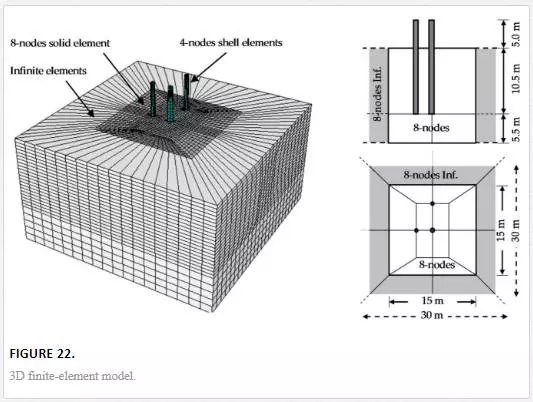
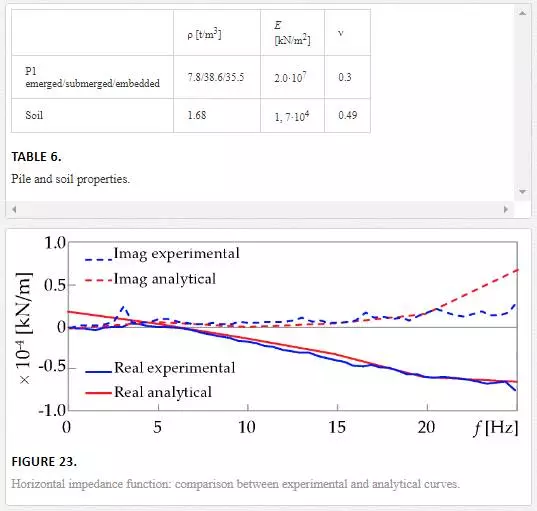
Finally, the obtained results at small and very small strains are compared with those derived from the dynamic soil-pile interaction 3D finite-element model developed in ABAQUS [45]. Soil domain was modeled as a parallelepiped (dimensions are reported in Figure 22) suitably partitioned into horizontal sublayers. 8-nodes solid elements were used for the soil domain, 4-nodes shell elements were used for the pipe piles, and 8-nodes infinite elements were used for the far field in order to avoid waves reflection/refraction along the boundaries. The mesh was suitably refined near the hammer impact point and in the soil surrounding the piles. With the energy of the impact being very low, the formation of gap along the soil-pile interfaces was excluded and the behavior of the system was considered linear elastic. Water surrounding the submerged portion of the piles was considered as an added mass and the impact of the hammer was reproduced as a uniform pressure applied on a surface equal to the hammer impact zone, varying with time. Dynamic analyses were performed in the time domain, with a direct implicit integration procedure. The mechanical characteristics of the pile P1 and the soil are reported by Table 6.Figure 23 shows the comparison between experimental and theoretical impedance functions. A good agreement between the experimental results and the theoretical predictions is observed within a significant frequency range, which largely covers the range of interest in engineering practice. Many other theoretical models could be used for the comparison with the experimental results: single pile model based on boundary elements or single pile model on Winkler foundation. Furthermore, in order to evaluate the behavior of the soil-water-pile system at higher strain levels, more advanced finite-element models should be developed with nonlinear constitutive relations in order to take into account the soil nonlinearities revealed by the snap-back test at increase load levels.
Conclusions
In this chapter, several in situ dynamic testing methods for the dynamic characterization of open-ended pipe piles in marine environment have been described. Different test typologies, the ones without any control on the input (such as ambient vibration test) and the ones where the excitation is artificially induced (such as impact load test and free vibration test), have been illustrated. Some attention has been given to the appropriate sensors to be used and to the suitable protection from marine environment and pile driving installation procedure. Furthermore, the most common signal processing techniques useful for handling the experimental raw signals have been addressed together with the analysis techniques for the evaluation of the modal parameters: natural frequencies, damping ratios, and mode shapes. In the last section, a concrete case study has been reported: an experimental campaign was carried out on near-shore open-ended pipe piles at the ‘‘Mirabello’’ harbor in La Spezia, Italy. During this campaign, impact load and snap-back tests have been performed and the modal properties of the soil-water-pile system have been identified by means of experimental modal analyses at both low and high strain levels. Some considerations can be formulated:
· Impact load test permits to evaluate the behavior of piles in marine environment at very low level of strain, whereas snap-back tests permit at both low and high levels; forced vibration test allows a more accurate evaluation of the modal parameters, whereas ambient vibration tests are especially suited for long-term monitoring.
· Accelerometers at the pile head allow the identification of natural frequencies and damping ratios, whereas strain gauges (electrical or fiber optic for long-term monitoring) along the pile length can be used to identify also the mode shapes.
· The accurate choice of the more appropriate instrumentation together with the most powerful protective systems is crucial in order to obtain successful results.
· Finally, for the estimation of the modal parameters of piles embedded in marine environment, conventional signal processing techniques and modal analysis procedures can be applied.
