In normal operation the turbine-generator is synchronised with and connected into an electrical power system, comprising other generating units and an extensive network for distributing power to the consumer. Typically, in the UK, the power supplied at any instant is in the range 15 to 50 GW and many turbine-generators are needed in parallel to supply the power at a steady voltage and frequency.
Consumers expect to switch their loads on and off at will. On a large power system, the minute-by-minute fluctuations will be a small percentage of the total load. On a local power system, supplying only a few consumers from a small number of generating units, similar consumer demands may apply and the fluctuations may be a significant percentage of the total load.
Nevertheless, on both large and small systems, faults will occur, and to maintain safety in such an event protective equipment operates to open circuit-breakers to isolate the fault.
For the individual turbine-generator unit and its governing system, these power system requirements imply a need to withstand a full-load rejection safely and to provide appropriate contributions to system frequency regulation.
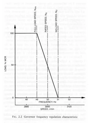
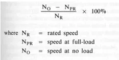
The main characteristic of a governing system is therefore the relationship between the generated load of the controlled machine and speed, which is the prime governor input. This is known as the speed-loop droop or frequency regulation characterstic of the governor and is shown in Fig 2.2. The steady state overall frequency regulation is defined as:
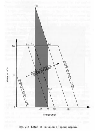
This regulation permits a machine to share load with other machines in a stable manner and also allows the operator to adjust the load contribution made by the machine relative to the others on the system. Figure 2.3 shows how the droop characteristic is varied by altering the speed setpoint. If the machine is at no-load and unsynchronised, point aj on the diagram, and the setpoint is raised, the frequency will change from a1 to a2 and then to a3. If, however, the machine is synchronised to an infinite system running at constant frequency aj, an increase in speed setpoint will cause the load to be raised to b2 and eventually to b3. It should be noted that the linear characteristics drawn are idealised; in practice they may be non-linear. Nevertheless, the degree of adjustment of the speed setpoint should permit no-load to be set at the lowest normal operating frequency and also full-load at the highest normal frequency, with a margin. Typically the range of operation is ±6% of nominal system frequency with the turbine unsynchronised at no-load.
Another feature to be noted from Fig 2.3 is the phenomenon of an ‘overwound’ speed setpoint. If the operator has set the unit to run at full-load at frequency f by adjusting the speed setpoint to give characteristic a3b3, then a fall in frequency by an amount A f will give a notional load of value c3. However, this value of load will not be attained, as the turbine valves are already fully open at point b3. The speed setpoint is said to be ‘overwound’. The disadvantage of this condition is that, if asked to reduce load on the unit, the operator is unable to do so immediately until he has reduced the speed setpoint to the line given by c2a2. Normal practice is either to draw the operator’s attention to the overwound condition by an alarm or to provide an automatic reduction at the setpoint so that an immediate response is possible, if required.
Facilities for droop adjustment are often provided. Typically a high value of droop, like 25%, may be beneficial in reducing transient steam pressure variations if the system frequency fluctuates to a marked degree. The droop may be adjustable within a range or alternatively switched from a selection of two or more values. Droop adjustment, or switching, on-load generally implies a load change unless carried out at the pivot point of the characteristic or unless coupled with a simultaneous change in speed setpoint. Many governors incorporate facilities for a ‘bumpless’ change in this fashion.
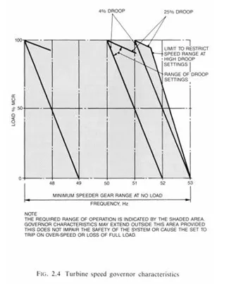
Figure 2.4 is a development of Fig 2.3, showing the characteristics of additional overspeed limiting facilities that have to be built into the design so that the speed rise on a load rejection can be adequately contained below the overspeed trip setpoint on a high droop governor. On a low droop governor (say 4% or less), the overspeed may be contained by the normal droop characteristic without any need for the special overspeed limiting facilities.
In either case, to meet the requirement of containing the overspeed within the trip setpoint, it will be necessary to close all the turbine valves within a fraction of a second. When the speed error reduces, the governor reopens the valves to the amount necessary to maintain the speed at the reduced value of load.
On reheat machines such as that depicted in Fig 2.1, it is necessary to control not only the HP governing valves but also the interceptor governing valves following the reheater. If the HP valves only were closed rapidly on a full-load rejection, the amount of stored steam in the reheater and associated pipework would be sufficient to overspeed the machine to destruction. Therefore, similar rapid response to close the interceptor governing valves is provided.
Most large turbine-generators employ reheating of the intermediate pressure (IP) steam to improve thermal efficiency. Thermal efficiency is reduced if throttling takes place in the interceptor valves, so these valves are usually fully open over the normal load range of the machine. This operating regime is referred to as HP governing and is achieved by applying a fixed bias to the interceptor governing valves, thus giving them the same speed/load characteristics as the HP governor valves but more open by the amount of the fixed bias (typically 50%). In the event of an overspeed, these valves will close, albeit at a greater speed-error than the HP governor valves.
Another possible mode of operation (often provided as a switched option) is to allow the interceptor governing valves to operate in a throttled condition. Although the thermal efficiency is reduced, ‘the spinning spare capability’ of the plant is enhanced: the capability of the machine to increase load rapidly in response to either a reduction in the power system frequency or a demand by the operator to increase load. This may be important in power systems where there are large fluctuations in network frequency, or where there are insufficient machines with good regulating characteristics. This mode of control is referred to as HP plus IP governing or sometimes as parallel governing. In the HP governing mode, the reheater pressure is normally proportional to the load on the machine, but in the HP plus IP governing mode, the aim is for a constant re-heater pressure, at least over the load range of 50-100%. This means that at 50% load, instead of the pressure in the reheater being say 20 bar, it will be at the full-load value of 40 bar and the ‘spinning spare’ capability will be improved by the additional thermal storage available through having reheater steam at the full-load pressure. Thus the IP and LP cylinders will be able to provide their full-load torque almost immediately, although there may later be some decay until the boiler firing rate has picked up to its full-load value.
The characteristics described so far in this section are those that suit the parallel connection of turbine-generators onto the power system. However, some of the features of a governing system arise from a consideration of the types of plant being controlled and the way in which the control of the separate boiler and turbine units is integrated to form an overall Station Control scheme. The purpose of this description is to note the main features affecting the governor. Three basic options are described, each of which may include enhancements (not described) to improve the response to particular operational circumstances.