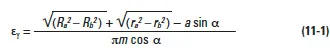
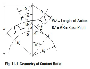
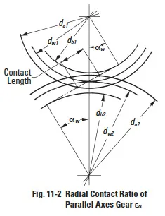
To assure continuous smooth tooth action, as one pair of teeth ceases action a succeeding pair of teeth must already have come into engagement. It is desirable to have as much overlap as is possible. A measure of this overlap action is the contact ratio. This is a ratio of the length of the line-of-action to the base pitch. Figure 11-1 shows the geometry for a spur gear pair, which is the simplest case, and is representative of the concept for all gear types. The length-of-action is determined from the intersection of the line-of-action and the outside radii. The ratio of the length-of-action to the base pitch is determined from:
It is good practice to maintain a contact ratio of 1.2 or greater. Under no circumstances should the ratio drop below 1.1, calculated for all tolerances at their worst case values.
A contact ratio between 1 and 2 means that part of the time two pairs of teeth are in contact and during the remaining time one pair is in contact. A ratio between 2 and 3 means 2 or 3 pairs of teeth are always in contact. Such a high ratio is generally not obtained with external spur gears, but can be developed in the meshing of internal gears, helical gears, or specially designed nonstandard external spur gears.
When considering all types of gears, contact ratio is composed of two components:
- Radial contact ratio (plane of rotation perpendicular to axes), εα
- Overlap contact ratio (axial), εβ
The sum is the total contact ratio, εɣ.
The overlap contact ratio component exists only in gear pairs that have helical or spiral tooth forms.
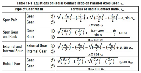
11.1 Radial Contact Ratio Of Spur And Helical Gears, εα
The equations for radial (or plane of rotation) contact ratio for spur and helical gears are given in Table 11-1, with reference to Figure 11-2.
When the contact ratio is inadequate, there are three means to increase it. These are somewhat obvious from examination of Equation (11-1).
- Decrease the pressure angle. This makes a longer line-of-action as it extends through the region between the two outside radii.
- Increase the number of teeth. As the number of teeth increases and the pitch diameter grows, again there is a longer line-of-action in the region between the outside radii.
- Increase working tooth depth. This can be done by adding addendum to the tooth and thus increase the outside radius. However, this requires a larger dedendum, and requires a special tooth design.
An example of helical gear: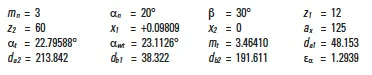
Note that in Table 11-1 only the radial or circular (plane of rotation) contact ratio is considered. This is true of both the spur and helical gear equations. However, for helical gears this is only one component of two. For the helical gear’s total contact ratio, εɣ, the overlap (axial) contact ratio, εβ, must be added. See Paragraph 11.4.
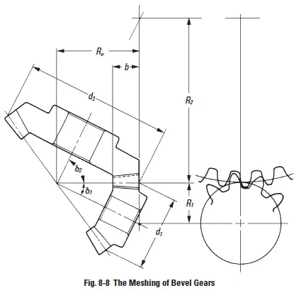
11.2 Contact Ratio Of Bevel Gears, εα
The contact ratio of a bevel gear pair can be derived from consideration of the equivalent spur gears, when viewed from the back cone. See Figure 8-8.
With this approach, the mesh can be treated as spur gears. Table 11-2 presents equations calculating the contact ratio.
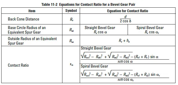
An example of spiral bevel gear (see Table 11-2):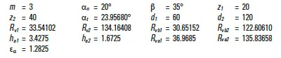
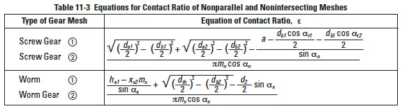
11.3 Contact Ratio For Nonparallel And Nonintersecting Axes Pairs, ε
This group pertains to screw gearing and worm gearing. The equations are approximations by considering the worm and worm gear mesh in the plane perpendicular to worm gear axis and likening it to spur gear and rack mesh. Table 11-3 presents these equations.
Example of worm mesh: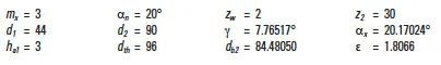
11.4 Axial (Overlap) Contact Ratio, εβ
Helical gears and spiral bevel gears have an overlap of tooth action in the axial direction. This overlap adds to the contact ratio. This is in contrast to spur gears which have no tooth action in the axial direction.
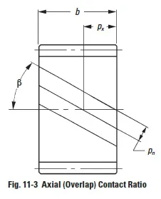
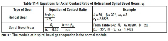
Thus, for the same tooth proportions in the plane of rotation, helical and spiral bevel gears offer a significant increase in contact ratio. The magnitude of axial contact ratio is a direct function of the gear width, as illustrated in Figure 11-3. Equations for calculating axial contact ratio are presented in Table 11-4.
It is obvious that contact ratio can be increased by either increasing the gear width or increasing the helix angle.