Inversions of mechanism: A mechanism is one in which one of the links of a kinematic chain is fixed. Different mechanisms can be obtained by fixing different links of the same kinematic chain. These are called as inversions of the mechanism. By changing the fixed link, the number of mechanisms which can be obtained is equal to the number of links. Excepting the original mechanism, all other mechanisms will be known as inversions of original mechanism. The inversion of a mechanism does not change the motion of its links relative to each other.
Four bar chain:

Fig 1.22 Four bar chain
One of the most useful and most common mechanisms is the four-bar linkage. In this mechanism, the link which can make complete rotation is known as crank (link 2). The link which oscillates is known as rocker or lever (link 4). And the link connecting these two is known as coupler (link 3). Link 1 is the frame.
Inversions of four bar chain:

Fig.1.23 Inversions of four bar chain.
Crank-rocker mechanism: In this mechanism, either link 1 or link 3 is fixed. Link 2 (crank) rotates completely and link 4 (rocker) oscillates. It is similar to (a) or (b) of fig.1.23.

Fig.1.24
Drag link mechanism. Here link 2 is fixed and both links 1 and 4 make complete rotation but with different velocities. This is similar to 1.23(c).

Fig.1.25
Double crank mechanism. This is one type of drag link mechanism, where, links 1& 3 are equal and parallel and links 2 & 4 are equal and parallel.

Fig.1.26
Double rocker mechanism. In this mechanism, link 4 is fixed. Link 2 makes complete rotation, whereas links 3 & 4 oscillate (Fig.1.23d)
Slider crank chain: This is a kinematic chain having four links. It has one sliding pair and three turning pairs. Link 2 has rotary motion and is called crank. Link 3 has got combined rotary and reciprocating motion and is called connecting rod. Link 4 has reciprocating motion and is called slider. Link 1 is frame (fixed). This mechanism is used to convert rotary motion to reciprocating and vice versa.

Fig1.27
Inversions of slider crank chain: Inversions of slider crank mechanism is obtained by fixing links 2, 3 and 4.

Rotary engine – I inversion of slider crank mechanism. (crank fixed)

Whitworth quick return motion mechanism–I inversion of slider crank mechanism.

Fig.1.30
Crank and slotted lever quick return motion mechanism – II inversion of slider crank mechanism (connecting rod fixed).

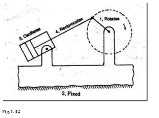
Oscillating cylinder engine–II inversion of slider crank mechanism (connecting rod fixed).
Pendulum pump or bull engine–III inversion of slider crank mechanism (slider fixed).
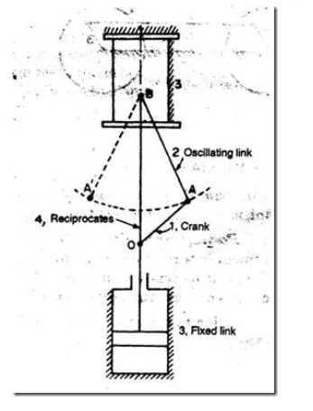
Fig.1.33
Double slider crank chain: It is a kinematic chain consisting of two turning pairs and two sliding pairs.
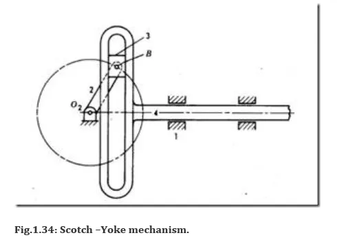
Scotch –Yoke mechanism.
Turning pairs – 1&2, 2&3; Sliding pairs – 3&4, 4&1.
Inversions of double slider crank mechanism:
Elliptical trammel. This is a device which is used for generating an elliptical profile.
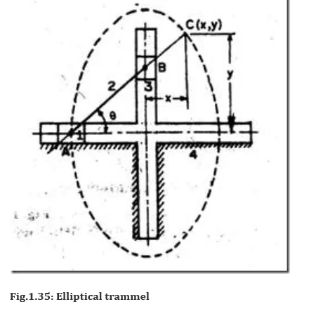
In fig. 1.35, if AC = p and BC = q, then, x = q.cosθ and y = p.sinθ.
This is the equation of an ellipse. The path traced by point C is an ellipse, with major axis and minor axis equal to 2p and 2q respectively.
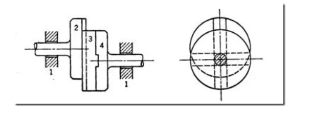
Oldham coupling. This is an inversion of double slider crank mechanism, which is used to connect two parallel shafts, whose axes are offset by a small amount.


Comments are closed