Every mechanism has moving members which move relative to each other about the joints connecting them. These relative motions result in the trajectories of the points on members of the mechanism. In any mechanism one link or member is fixed and acts as the frame. The trajectories and motion characteristics of mechanism depend on the choice of the reference frame link.
Inversions of a mechanism are the different configurations of the mechanism with change of the fixed reference link called frame. For different inversions of a mechanism although the motion characteristics are entirely different but the relative angular displacements of the members remain unchanged irrespective of the link chosen as frame.
The information obtained from one inversion of the linkage can be used to study other inversions of that linkage. Inversion technique is used extensively for analysis and synthesis of mechanisms.
Determining the Inversions of a Mechanism
Before going into details of obtaining inversions of a mechanism I would like to make it very clear that Inverse Kinematics is different from Kinematic Inversion. Read more about Inverse Kinematics.
Every mechanism is formed of a kinematic chain. When one of the links in the kinematic chain is fixed it becomes a mechanism. To determine the inversions of a mechanism consider the kinematic chain forming the mechanism and obtain the desired inversions by fixing any one of the members as the frame link.
Inversions of a Four-Bar Mechanism
A typical four bar mechanism, as the name denotes, is formed of a kinematic chain of four members connected by revolute joints. This mechanism can have four possible configurations with a different link fixed as frame each time.
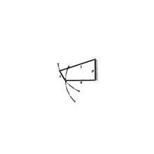
Configuration 1
Link 1 is taken as the base link or frame. In this configuration the shortest link is jointed to the base link and this joint can fully rotate and hence called as crank. The other link jointed to the base link oscillates and called as a rocker. This configuration of the four-bar kinematic chain is called as Crank-Rocker mechanism.
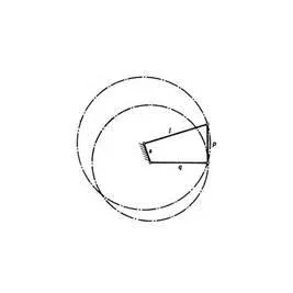
Configuration 2
Link 2 is fixed as the base link. In this configuration shortest link is the base and both joints to the base can rotate completely. It is thus called as Double-Crank or a Drag-Link.
Configuration 3
Link 3 is fixed as the base link. It can be observed that this configuration is same as the Crank-Rocker mechanism.
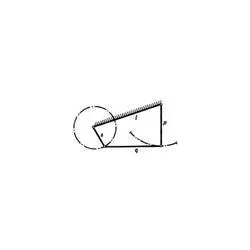
Configuration 4
Link 4 is fixed as the base link. In this configuration shortest link is the coupler and both the links connected to the base link cannot rotate fully, both oscillate. In this configuration the four-bar kinematic chain is called as Double-Rocker mechanism.