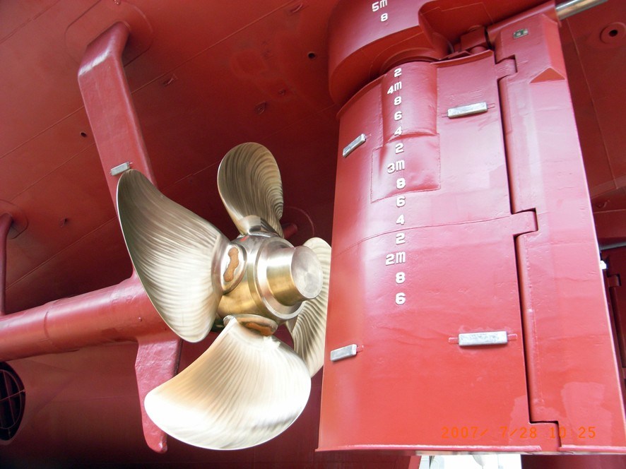
To broadly categorize conventional rudders, there are two types of ship rudders:
1. Spade or Balanced Rudder
A spade rudder is basically a rudder plate that is fixed to the rudder stock only at the top of the rudder. In other words, the rudder stock (or the axis of the rudder) doesn’t run down along the span of the rudder. The position of the rudder stock along the chord of the rudder (width meaning, from the forward to aft end of the rudder) actually decides whether the rudder is balanced of semi-balanced one. In balanced rudders, (which spade rudders generally are) the rudder stock is at such a position such that 40% of the rudder area is forward of the stock and the remaining is aft of it.
A genuine question that must have come up in your mind is, why is such a position chosen for the rudder stock? The answer lies in simple physics. The centre of gravity of the rudder will lie somewhere close to 40% of its chord length from its forward end. If the axis of the rudder is placed near to this location, the torque required to rotate the rudder will be much lesser than what is required to move it, had the axis been placed at the forward end of the rudder. So, the energy requirement of the steering gear equipment is reduced, therefore lowering the fuel consumption of the ship.

2. Unbalanced Rudders
These rudders have their stocks attached at the forward most point of their span. Unlike balanced rudders, the rudder stock runs along the chord length of the rudder. The reason is simple. In this case, the torque required to turn the rudder is way higher than what is required for a corresponding balanced rudder. So, the topmost part of the rudder has to be fixed to the spindle so as to prevent it from vertical displacement from its natural position. However, unbalanced rudders are not widely used now.
Having discussed the conventional types of rudders, let us shift into something yet more interesting. Researchers and ship operators had found significant problems with the balanced and unbalanced rudders. That is, in case there was a failure of the steering gear mechanism while turning a ship. The rudder would remain still with its angle of attack in that condition. The solution to this was found in designing an optimized Semi-Balanced Rudder.

a. Semi- Balanced Rudder:
If you have been able to visualize a balanced and unbalanced rudder by now, it should be pretty easy to visualize a semi-balanced rudder. In fact, the rudder you see on most ships are semi-balanced in the modern industry. The name semi-balanced itself implies, that the rudder is partly balanced and partly unbalanced. If you refer to the figure below, you’ll see that a portion of the chord length from the top is unbalanced, and the remaining chord length is balanced. Why? Read on.
The top part being unbalanced will help in acting as structural support to the rudder from vertical displacement. And the balanced part will render less torque in swinging the rudder. As a result, a semi-balanced rudder returns to the centreline orientation on its own if the steering gear equipment fails during a turn.

Note in the above figure the Rudder horn. Semi-balanced rudders are again of two types depending upon the depth of the horn (which affects the response and torque characteristics of the rudder). A shallow horn rudder will have a horn which extends hardly half the chord length of the rudder from the top. Whereas, a deep horn rudder will feature a horn deeply extending up to more than 50 % of its chord length from the top of the rudder.
Apart from these, designers have developed some other, rather unconventional rudder systems, which gets more interesting to look into.
b. Flaps Rudder:
You must have watched an aeroplane’s wings closely. Did you watch those flaps coming in and out of the aft end of the wing? Why do you think they do that? Primarily to change the effective angle of attack of the entire aerofoil section of the wing. You’ll see, during a takeoff, how all the flaps are completely deployed. That actually helps in attaining the effective angle of attack so as to get the maximum lift force.
The same principle, when used in rudders, provides a similar result. Just that, in case of rudders, the flaps are not retractable and they have their significant effects when the rudder is given some angle of attack.

c. Pleuger Rudder:
Perhaps one of the most innovative rudder mechanisms you will ever come across. Suppose you have a ship, too large to be manoeuvre in a basin with size constraints, such that the ship cannot use its propeller during the manoeuvre. This situation often arises in case of large ships operating in space-constrained basins, or in any case of low-speed manoeuvres.
So, a Pleuger rudder (as you can see in the figure below), has a smaller auxiliary propeller housed within it (which runs by a motor). As this housing is mounted on the rudder itself, it generates a thrust (which is smaller than what is generated by the ship’s main engine propeller) in a direction that is oriented along the rudder, therefore allowing effective manoeuvre in slow speed condition.

Such a rudder can be used in normal conditions also. Just that, in normal speeds, the Pleuger is not operated. However, when the Pleuger is run, the main engine propeller must not be operated simultaneously, which will otherwise cause the Pleuger to be torn away.


Comments are closed