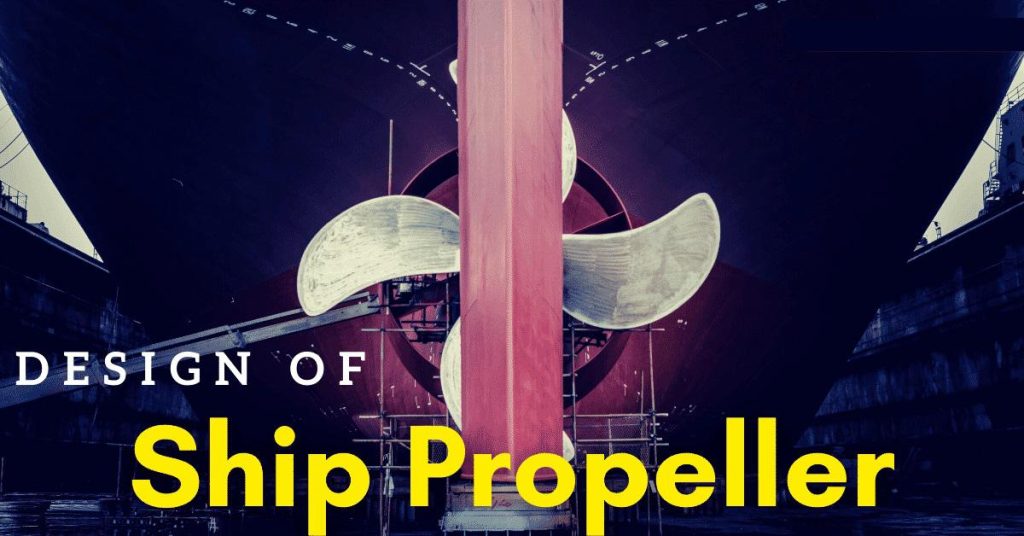
Ship propeller is used for propulsion in most types of vessels, irrespective of their type and size. The notion of ‘pushing’ or ‘propelling’ a ship forward came into being since the advent of ships themselves. After the era of those large sails governing the manoeuvrability and powering the ship, propellers became the most conventional means of driving the ship in the seas.
We are familiar with seeing propellers fitted behind the ships, but have we ever contemplated upon the shape, appearance and typical geometry of a propeller? Is there some physics behind the unusual nature of marine propellers as contrary to the normal flat-bladed fans we are accustomed to seeing in our day-to-day lives?
1. Manoeuvrability and variation of speed
2. Overcoming the resistance encountered by the vessel at sea

Figure 1. Propeller behind a ship
Resistance, as we are aware of is a principal phenomenon inevitable in all bodies floating in real fluids. As the seawater under all circumstances is adhering to both viscous effects as well as waves, resistance is substantial. Thus, in today’s time, we cannot envisage large ships and submarines without propellers. Furthermore, newer and better designs of propellers conceptualised from modern software tools and advanced experimentation methods aimed for higher efficiency are taking birth to improve the performance of ships at sea.
Propulsion is vast pastureland in the field of naval architecture. But before delving deeper, it is crucial to go through the fundamentals in the geometry of ship propeller.

What does a ship propeller look like?
Propeller Hub or Boss
Analogous to a traditional table fan, a ship propeller has a central boss which is like the backbone of the entire arrangement. It mates with the rotating shaft which corroborates with the engine room mechanism. The shaft transmits the power delivered from the engine (with losses, of course!) and in turn, rotates the blades mounted on the hub/boss. Detailed studies of hydrodynamic behaviour of propellers in different water conditions have shown that the delivered thrust and thus the resultant efficiency is inversely proportional to the size/diameter of the boss. Thus, modern designs have evolved with the smaller yet stronger boss so as also to maintain a safety trade-off in terms of strength. Figure 2 below shows a simple illustration.

Figure 2. Blade mounted on a propeller hub
Propeller Blades

To a commoner, blades are synonymous with the propellers themselves. Blades are mounted on the hub similar to thin aerofoil sections which can create a hydrodynamic lift required to produce thrust. Over time blades have evolved into innumerable designs and shapes foiled, twisted and torqued in a typical manner apt for the vessel at design speed and displacement.
Irrespective of the aesthetics in the blade design, all propeller has a set of common features worth knowing. They are:
Blade Face and Back
The ship propeller has two hydrodynamic surfaces: Face and Back. To put it simply, the cross-section of blades coupled with the boss when looked from behind the ship is called the Face, also known as the ‘palm’. The opposite face is called Back.
Figure 3 illustrates better.

Figure 3. Plan of a propeller section showing face and back
Leading Edge and Trailing Edge
To be put simply, there are two edges of a ship propeller blade. The edge which pierces the water surface first in order of succession is termed as the Leading Edge. Depending upon the sense of rotation of the propeller (whether it rotates clockwise or anticlockwise), either of the two edges can become the leading edge. The other edge, which follows or ‘lags behind’ the leading edge is termed as the Trailing Edge. The following figure shows better.

Figure 4. Leading and Trailing Edges of a blade
Figure 4. Leading and Trailing Edges of a blade
Root and Tip
The point of attachment of the blades with the ship propeller boss or hub is called the root. Tip is the furthest point of the propeller blade from the root and tapers like a leaf. It has the least section width. It joins the leading and trailing edges as well as remains the same for the face and the back.
This is clearly shown in figure 5.

Figure 5. Root and Tip of a propeller blade
Design of ship propeller – Choosing the Suitable Reference
Every physical entity has to be defined with respect to a suitable reference frame. In propellers too, a uniform Cartesian coordinate system has to define beforehand. Although the choice of reference in x, y and z planes is arbitrary, a common ‘Convention’ is taken such that the x-axis is along the direction of the shaft axis, y-axis is perpendicular to the shaft axis (sideways) and the z-axis is in-plane to the ship propeller blade area as shown in the figure.

Figure 6. The Conventional system of Reference
The Concept of Pitch
We are familiar with the simple physics behind screws from our school days. Pitch is defined as the lateral distance traversed by a fixed point when the screw turns about its own axis. It is exactly the same in case of propellers. Maybe that is the reason why these propellers are also alluded to as ‘Screw Propellers’!

Pitch in case of a propeller is a measure of how much the propeller would “drive” or “Push forward” when it is freely turned about its own axis. So, an obvious question that may arise in your minds is: Does the propeller actually displace forward?
The answer is no. It is coupled through an intrinsic shafting mechanism to the main engine. But validating Newton’s third law, it generates a reaction force in the wake region astern which thrusts the vessel forward. That is the reason priming the ship propeller to such a crucial task in propelling the vessel forward. Thus, the pitch may be denoted as “The unit distance moved by a point on a propeller when the propeller completes one revolution.”

Figure 7. Variation of pitch along the length of the propeller blade
Further analysis of pitch involves much more mathematical paradigms which are not discussed here. But one crucial aspect to ponder upon is the fact that the distance calculated from normal pitch calculations is overestimated as compared to the actual distance travelled by ship in one propeller revolution. The reason is obvious. There are unavoidable losses due to resistance (viscous and wave-making) and other factors such as losses in the engine-shafting mechanism, wave-induced events in the slipstream and cavitation. The following figure depicts the geometric details of pitch.
Understanding Rake and Skew for ship propeller design Rake
When the propeller is viewed from sideways, we see that the blades of the propeller are not perpendicular to the surface of the hub. It is ‘tilted’ at an angle either towards the fore-end or the aft end of the ship. This is termed as Rake. The angle or the inclination of the rake in its profile is dependent on the vessel design, capacity, speed and other structural factors.
One of the biggest reasons for the rake is allowing higher clearance between the blades and the vicinal hull surface. If the blade tip happens to be very close to the hull plating (which is very prone in case of no or little raked ones), there is a chance of induced vibration due to ship propeller action. This is obviously not congenial from both propulsions as well as the structural point of view. For a particular vessel type, there is a maximum and minimum allowable clearance of the blade tip.
As discussed earlier in the context of the reference frame, the rake is a deviation in X-Z plane ‘longitudinally’ in the shaft direction. When the blade is raked forward, that is in the direction of the shaft axis towards fore-end, it is called Negative Rake. Conversely, when it is raked aft, it is called Positive Rake (See Figure).

Fig 8. Profile of Propeller Blade showing Rake
Skew
We now shift our reference to the Y-Z plane (which appears when we look at the ship propeller surface from behind). The blade appears to be ‘Skewed’, that is, bent or twisted sideways. The skew of a propeller is clearly shown in the following figure.

Figure 9. (a) No skew (b) Skew in a propeller blade
There are practically two types of skew: Balanced and unbalanced.
· The former is skew within lesser limits, where the generator line intersects the datum line at least two points. These types of ship propellers are known as ‘moderately skewed’.
· On the other hand, unbalanced skew is a higher degree of deviation where the generator line intersects the reference line at not more than one point (considerably higher range of skew). They are said to be ‘heavily skewed’.
The following figure gives an illustration of the two types of skew.

Figure 10. (a) Balanced (b) Heavily Skewed Propeller Blades
We know well that, the flow in the wakefield is highly unsteady and unpredictable (behind the propeller). This is further modified by propeller action. After years of experimentation, analysis and sea trials, it was observed that aptly skewing a ship propeller nullifies or considerably minimises the extent of unsteady hydrodynamic loading in this flow field. This indirectly has positive effects in reducing resistance due to viscous ‘drag’ effects.
Thus we conclude by saying that in ship design and building process, design of ship propellers play a catalytic role. Thus the basic knowledge of propellers is useful for designers to optimise its design aesthetics for various working loads and types of operations, aimed at achieving maximum efficiency.


